
Data Sheet
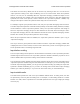
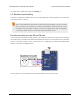
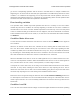

Example Tic scaling settings for RC
position control mode.
• Any input value greater than the input maximum
gets mapped to the target maximum.
• Any input value between the input neutral max and
the input maximum gets mapped to a number
between 0 and the target maximum.
• Any input value between the input neutral min and
input neutral max gets mapped to 0.
• Any input value between the input minimum and
input neutral min gets mapped to a number
between the target minimum and 0.
• Any input value less than the input minimum gets
mapped to the target minimum.
When the “Invert input direction” checkbox is checked, it changes the scaling so that higher input
values correspond to lower target values. You can think of it as simply switching the target maximum
and target minimum in the rules above.
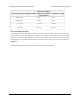
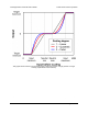
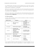
The scaling degree can be set to “1 – Linear”, “2 – Quadratic”, or “3 – Cubic”. With the default setting
of “1 – Linear”, the scaling function is linear. If you choose a higher scaling degree, then the Tic uses
a higher-degree polynomial function, which can give you finer control when the input is closer to its
neutral position. With linear scaling, if the input is one quarter (1/4) of the way from the input neutral
max to the input maximum, the target will be one quarter (1/4) of the target maximum. With quadratic
scaling, the output would be one sixteenth (1/16) of the target maximum. With cubic scaling, the output
would be one sixty fourth (1/64) of the target maximum.
The input maximum, input neutral max, input neutral min, and input minimum must be between 0 and
4095. The target maximum must be between 0 and +2,147,483,647, while the target minimum must
be between 0 and -2,147,483,647.
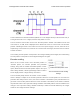
Analog/RC input state
When the Tic’s control mode is analog or RC, the Tic’s “Input state” variable starts off in the “not ready”
state when the Tic starts running and has not yet collected its first set of analog readings or detected
the RC signal. The Tic leaves this state quickly (usually within 100 ms). After that, the Tic’s input state
will be in “invalid” if its RC input signal is missing or bad. There is currently no concept of an analog
signal being invalid, so the analog control modes do not use that state. If the analog/RC input is valid,
then the input state variable will either be “Target position” or “Target velocity” depending on what
control mode was selected. This indicates that the Tic has successfully read its input and populated
the “Input after scaling” variable with either a target position or a target velocity. For details about how
Tic Stepper Motor Controller User’s Guide © 2001–2018 Pololu Corporation
5. Details Page 65 of 150