
Data Sheet

This setting can be temporarily overridden using the “Set starting speed” command, as described in
Section 8.
The “Starting speed” uses the Tic’s standard speed units of 10,000 pulses per second.
Max acceleration and max deceleration
The “Max acceleration” setting specifies how rapidly the speed is allowed to increase, while the “Max
deceleration” setting specifies how rapidly the speed is allowed to decrease. See Section 4.3 for tips
about choosing these settings.
These settings can be temporarily overridden using the “Set max acceleration” and “Set max
deceleration” settings, as described in Section 8. However, note that the “Set max acceleration”
command never changes the “Max deceleration” value, even if the “Use max acceleration limit for
deceleration” checkbox is checked.
Both of these settings use units of pulses per second per 100 seconds. In other words, they specify
how much the speed can rise or fall in one hundredth of a second (0.01 s or 10 ms). The range of
allowed values is 100 to 2,147,483,647.
5.2. Analog/RC input handling
This section documents the details of how the Tic reads its analog and RC inputs and how it averages,
filters, and scales those inputs in order to set a target velocity or target position.
Analog readings on the SDA pin
When the SDA pin is configured as an analog input, the Tic regularly uses its 10-bit ADC to take
readings of the voltage on the pin. After it completes 8 ADC readings, it adds the readings together
and multiplies by 8 to get a number between 0 and 65,472 which it stores in the “Analog reading SDA”
variable. The “Analog reading SDA” variable, like most of the variables in this section, can be read
from the Tic over USB, serial, or I²C, and is listed in Section 7.
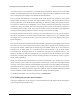
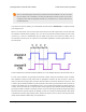
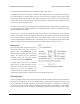
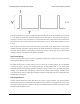
Pulse measurement on the RC pin
The Tic measures the width of RC pulses on its RC input pin. The signal on the RC pin should look
like the waveform shown below:
Tic Stepper Motor Controller User’s Guide © 2001–2018 Pololu Corporation
5. Details Page 59 of 150