
Data Sheet
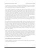
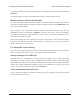
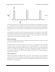

The STEP and DIR lines are pulled down by default. The driver takes one step whenever it sees
a rising edge on the STEP pin, and the direction of the step is specified by the DIR pin. See the
DRV8825 datasheet [https://www.pololu.com/file/download/drv8825.pdf?file_id=0J590] (1MB pdf) for detailed
specifications of the STEP/DIR interface on the Tic T825, or see the DRV8834 datasheet
[https://www.pololu.com/file/download/drv8834.pdf?file_id=0J617] (2MB pdf) for detailed specifications of the
STEP/DIR interface on the Tic T834.
In STEP/DIR mode, the Tic’s USB, serial, and I2C interfaces can still be used to set the driver’s current
limit, decay mode, and step mode, or to de-energize the driver.
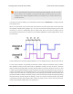
Alternatively, when the Tic’s control mode is set to anything other than “STEP/DIR”, you can use the
STEP and DIR pins as outputs to control an external stepper motor driver. However, you will still need
to supply power to the Tic’s VIN pin, or else the Tic will report a “Low VIN” error and not attempt to
drive the motor.
Tic Stepper Motor Controller User’s Guide © 2001–2018 Pololu Corporation
4. Setting up the controller Page 55 of 150