
Data Sheet

applicable). If you have access to an oscilloscope, you should check the signals on RX and TX. If the
“Encoder position” is responding properly to the encoder but the “Input after scaling” variable is not,
then make sure you set the Tic’s input settings as described above. The Tic expresses velocities in
units of pulses per 10,000 seconds, so if the “Input after scaling” is a non-zero number that is much
smaller than 10,000, your motor might be moving, but it would be moving too slowly to be easily
noticed. Make sure you have set the encoder postscaler as described above.
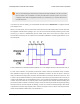
The Tic expects that transitions on its encoder inputs will be at least 100 µs apart. If your encoder
signal is faster than this, the Tic might miss some encoder counts or could even measure counts in
the wrong direction. To see whether this is happening, you should try turning your encoder as fast as
you expect it to be turned in your application. As you do this, look at the “Encoder skip” count shown
in the “Errors” box in the “Status” tab. If the count goes up when you turn the encoder, that means the
Tic is missing some encoder counts. In that case, if encoder accuracy is important in your application,
you might consider getting a different encoder or turning your encoder more slowly.
You should make sure that the motor is moving in the correct direction. If it is not, you can swap the
RX and TX connections or check the “Invert motor direction” checkbox to fix it. (You could also rewire
the stepper motor to reverse the current in one coil, but be sure to turn off the stepper motor power
before doing that.)
Finally, you should set the encoder prescaler and postscaler to specify how much the stepper motor
speed should change as you turn the encoder. Every time the encoder position changes by the
prescaler amount, the “Input after scaling” variable will be changed by the postscaler amount. So if
you increase the prescaler from its default value of 1, it will take more encoder movement to get the
same change in speed from the stepper motor. If your encoder has detents, it usually makes sense
to set the encoder prescaler to the number of counts you get per detent, which is typically 4. If you
decrease the postscaler, you will have finer control of the motor speed and it will take more turns of
the encoder to reach full speed. If you increase the postscaler, you will have coarser control over the
motor speed, and it will take fewer turns to reach full speed.
For details about how the Tic’s encoder input works, see Section 5.3.
4.13. Setting up STEP/DIR control
You can set the Tic’s control mode to “STEP/DIR” to turn the Tic into a digitally-configurable stepper
motor driver [https://www.pololu.com/category/120/stepper-motor-drivers].
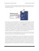
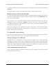
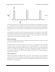
In this mode, you will need to connect a microcontroller to the Tic’s STEP and DIR pins to control the
stepper motor. The STEP and DIR pins are connected through 470 Ω protection resistors to the STEP
and DIR inputs on the Tic’s on-board stepper motor driver IC; using them to control the driver bypasses
the Tic’s speed-limiting and acceleration-limiting features, and the Tic will have no knowledge of the
current position or speed of the stepper motor.
Tic Stepper Motor Controller User’s Guide © 2001–2018 Pololu Corporation
4. Setting up the controller Page 54 of 150