
Data Sheet

The Tic does not support closed-loop control with encoder feedback. The Tic’s encoder
input is meant to be connected to a rotary encoder that is turned by hand. If you have
a stepper motor with an integrated encoder, you should not try to connect the motor’s
encoder to the Tic.
If you have not done so already, you should follow the instructions in Section 4.3 to configure and test
your stepper motor.
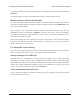
When in encoder mode, the Tic uses its RX and TX lines as encoder inputs. Each of these lines has
an integrated 100 kΩ resistor pulling it up to 5 V and a 470 Ω series resistor protecting it from short
circuits (e.g. in case it is inadvertently put into serial mode, which uses TX as an output, with an
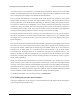
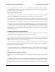
encoder still connected). The Tic expects to see standard quadrature encoder signals like this on its
encoder inputs:
The time between the channel transitions (labeled T
1-4
in the diagram above) must be at least 100 µs.
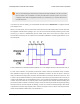
For this control interface, we generally recommend common three-pin mechanical rotary encoders
with quadrature outputs, though other kinds of quadrature encoders can also be used. A three-pin
rotary encoder has two signal pins, A and B, which should be connected to RX and TX on the Tic, and
a common pin (sometimes labeled “C”) that should be connected to ground. Note that the common pin
is often in the middle, but you should always refer to your encoder documentation to identify which pin
is which. These encoders do not require power as the signal pins just alternate between floating and
ground as the dial is rotated. The built-in pull-ups on the RX and TX pins make the signal high during
the times when the encoder outputs are floating, so there is no need for external pull-ups. Other kinds
of quadrature encoders might require power, and the 5V output on the Tic can be used to power them
if their documentation indicates they can operate at 5 V.
Tic Stepper Motor Controller User’s Guide © 2001–2018 Pololu Corporation
4. Setting up the controller Page 52 of 150