
Data Sheet


Section 5.2.
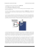
4.9. Setting up analog position control
This section explains how to set up the Tic to read an analog input and use that signal to control the
position of the stepper motor.
It is important to note that the Tic does not receive any kind of feedback from the stepper motor about
its position. When you power on the Tic, it does not know what position the stepper motor is in, so
it will read the analog input and then assume that the stepper motor is already at the position that
corresponds to that input. Also, there are other error conditions besides losing power that will cause
the Tic to become uncertain about its current position from the analog input when the system returns
to normal (see Section 5.4).
If you have not done so already, you should follow the instructions in Section 4.3 to configure and
test your stepper motor. Next, with the system unpowered, connect your analog signal to the Tic as
described below.
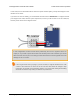
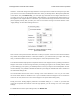
If you are using a potentiometer to make the analog signal, you should connect the potentiometer’s
wiper to SDA/AN and connect the other two ends to GND and SCL, as shown in the diagram below.
In analog mode, the SCL line is driven high (5 V) to power the potentiometer (note that the SCL pin is
protected by a 470 Ω series resistor, so it will not be damaged by inadvertent shorts to ground).
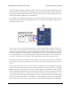
If you are using something other than a potentiometer to generate the analog signal, make sure that
the ground node of that device is connected to a GND pin on the Tic, and that the analog signal
from that device is connected to the Tic’s SDA/AN line. The Tic’s analog input can only accept signals
between 0 V and 5 V with respect to GND; signals outside of this range could damage the Tic.
Now connect the Tic to your computer via USB. In the Tic Control Center software, set the Tic’s control
Tic Stepper Motor Controller User’s Guide © 2001–2018 Pololu Corporation
4. Setting up the controller Page 45 of 150