
Data Sheet
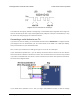
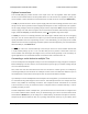
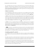

The following diagram shows the standard I²C connections described above along with optional
connections of the ERR and RST pins:
The ERR pins can all be safely connected together. In such a configuration, the line will be high if one
or more Tics has an error; otherwise, it will be low. Additionally, the Tics are configured by default to
treat a high signal on their ERR lines as an error, so an error on one Tic will trigger an error on all
other Tics when their ERR lines are connected as shown in the above diagram. This behavior can
be disabled by checking the “Ignore ERR line high” box under the “Advanced settings” tab of the Tic
Control Center. For more information on the ERR pin and error handling in general, see Section 5.4.
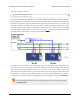
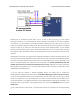
4.7. Setting up RC position control
This section explains how to set up the Tic to read a hobby RC servo signal and use that signal to
control the position of the stepper motor.
In this mode, the Tic will behave somewhat like an RC servo. One advantage of the Tic is that you can
set up the range of motion of your system to be very large (e.g. tens of turns) or very small (e.g. a few
degrees). One important difference between the Tic and an RC servo is that the Tic does not receive
any kind of feedback from the stepper motor about its position. When you power on an RC servo and
send it a signal, it immediately moves to the position corresponding to that signal. When you power
on the Tic, it does not know what position the stepper motor is in, so it will wait for a valid RC signal,
and then assume that the stepper motor is already at the position that corresponds to that signal. Also,
there are other error conditions besides losing power that will cause the Tic to become uncertain about
its current position and re-learn it when the system returns to normal (see Section 5.4).
1
2
TicI2C tic1(14);
TicI2C tic2(15);
?
Tic Stepper Motor Controller User’s Guide © 2001–2018 Pololu Corporation
4. Setting up the controller Page 40 of 150