
Data Sheet
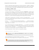
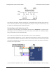
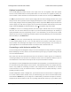
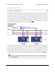
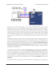
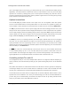
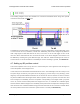

Diagram of a non-inverted TTL serial byte.
The serial lines are high by default. The beginning of a transmitted byte is signaled with a single low
start bit, followed by the bits of byte, least-significant bit (LSB) first. The byte is terminated by a stop
bit, which is the line going high for at least one bit time.
Connecting a serial device to one Tic
If you have not done so already, you should follow the instructions in Section 4.3 to configure and test
your stepper motor. You should leave your Tic’s control mode set to “Serial / I²C / USB” (the default),
and you should also set your desired baud rate.
Next, connect your serial device’s GND (ground) pin to one of the Tic’s GND pins.
If your serial device operates at 5 V, you can directly connect the device’s TX line to the Tic’s RX line
and connect the Tic’s RX line to the device’s TX line. The connection to the Tic’s TX line is only needed
if you want to read data back from the Tic. These connections, and some other optional connections,
are shown in the diagram below:
If your serial device operates at 3.3 V, then you might need additional circuitry to shift the voltage
Tic Stepper Motor Controller User’s Guide © 2001–2018 Pololu Corporation
4. Setting up the controller Page 33 of 150