
Data Sheet

10. I²C command encoding
As described in Section 8, the Tic’s I²C commands each use one of four formats: quick, 7-bit write,
32-bit write, and block read. This section explains how these four command formats are encoded as
sequences of bytes within I²C transfers.
For a reference implementation of this protocol, see the TicI2C class in our Tic Stepper Motor
Controller library for Arduino [https://github.com/pololu/tic-arduino].
Note that most of these formats are compatible with the SMBus protocols of the same names; an
exception is the block read command, although an SMBus-compatible workaround can be found in its
description below.
The default slave address for the Tic is 0001110b (0x0E in hex; 14 in decimal), but this is a setting
(“device number”) you can change. (This setting also determines the Tic’s device number when using
the Pololu protocol over TTL serial.)
As specified by the I²C standard, a transfer’s address byte consists of the 7-bit slave address followed
by another bit to indicate the transfer direction: 0 for writing to the slave, 1 for reading from the
slave. This is denoted by “addr + Wr” and “addr + Rd” below. With the Tic’s default slave address, the
address byte is 00011100b (0x1C) for a write transfer and 00011101b (0x1D) for a read transfer.
These symbols are also used in the format descriptions below:
• S: start condition
• P: stop condition
• A: acknowledge (ACK)
• N: not acknowledge (NACK)
Any stop condition followed by a start condition can optionally be replaced with a repeated start
condition.
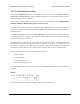
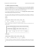
Quick
master: S addr + Wr command P
Tic: A A
A Quick command sends no data and simply consists of the command byte.
Tic Stepper Motor Controller User’s Guide © 2001–2018 Pololu Corporation
10. I²C command encoding Page 141 of 150