
Data Sheet


SDA the reading is not available. 5V pin
0x43
Analog
reading
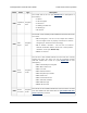
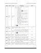
TX
unsigned
16-bit
Analog reading from the TX pin, if analog
readings are enabled for it. 0xFFFF means
the reading is not available.
0 = 0 V,
0xFFFE ≈ voltage on
5V pin
0x45
Analog
reading
RX
unsigned
16-bit
Analog reading from the RX pin, if analog
readings are enabled for it. 0xFFFF means
the reading is not available.
0 = 0 V,
0xFFFE ≈ voltage on
5V pin
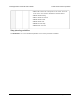
0x47
Digital
readings
unsigned
8-bit
Digital readings from the Tic’s control pins. A
set bit indicates that the pin is high.
• Bit 0: SCL
• Bit 1: SDA
• Bit 2: TX
• Bit 3: RX
• Bit 4: RC
• Bits 5–7: reserved
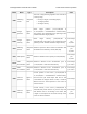
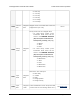
0x48 Pin states
unsigned
8-bit
States of the Tic’s control pins, i.e. what kind
of input or output each pin is.
• Bits 0–1: SCL
• Bits 2–3: SDA
• Bits 4–5: TX
• Bits 6–7: RX
Each group of two bits encodes a number
that represents one of the following states:
• 0: High impedance
• 1: Pulled up
• 2: Output low
• 3: Output high
Note that the reported state might be
misleading if the pin is being used as a TTL
serial or I²C pin. The state of the RC pin
cannot be set.
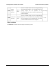
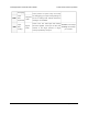
0x49
Step
mode
unsigned
8-bit
Step mode of the Tic’s stepper driver (also
known as microstepping mode), which
defines how many microsteps correspond to
one full step.
Tic Stepper Motor Controller User’s Guide © 2001–2018 Pololu Corporation
7. Variable reference Page 117 of 150