
Data Sheet
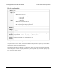

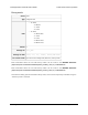

Switch polarity map
Offset 0x36
Type 8-bit
Data
• Bit 0: polarity of SCL pin if it is used as a switch
• Bit 1: polarity of SDA pin if it is used as a switch
• Bit 2: polarity of TX pin if it is used as a switch
• Bit 3: polarity of RX pin if it is used as a switch
• Bit 4: polarity of RC pin if it is used as a switch
• Bits 5–7: reserved, should be 0
Default 0
Settings file Listed in scl_config , sda_config , tx_config , rx_config , rc_config
Settings file data active_high or nothing
Tic Control Center Advanced settings tab, Pin configuration, Active high checkboxes
For each pin configured as a switch, this setting allows you to choose whether that pin is active high
or active low. If the pin’s switch polarity bit is 0, it is active low (a low voltage corresponds to an active
switch). If the bit is 1, it is active high.
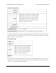
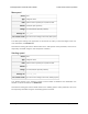
Kill switch map
Offset 0x5D
Type 8-bit
Data
• Bit 0: 1 if SCL pin is used as a kill switch
• Bit 1: 1 if SDA pin is used a kill switch
• Bit 2: 1 if TX pin is used as a kill switch
• Bit 3: 1 if RX pin is used as a kill switch
• Bit 4: 1 if RC pin is used as a kill switch
• Bits 5–7: reserved, should be 0
Default 0
This byte contains redundant information to make the firmware implementation simpler. Each of the
five input pins of the Tic has one bit in this byte. If the bit is 0, it means that the pin is not a kill switch.
If the bit is 1, it means that the pin is a kill switch.
Tic Stepper Motor Controller User’s Guide © 2001–2018 Pololu Corporation
6. Setting reference Page 102 of 150