
Data Sheet
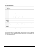

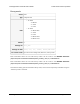

RC pin configuration
Offset 0x3F
Type 8-bit
Data
• Bits 0–3: Pin function:
◦ 0: Default (see below)
◦ 2: User input
◦ 5: RC input
◦ 7: Kill switch
• Bits 4–5: reserved, should be 0
• Bit 6: Ignored (cannot do analog readings)
• Bit 7: Ignored (pin is always pulled down)
Default 0
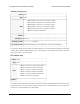
Settings
file
rc_config
Settings
file data
Space-separated list including a subset of pin options ( active_high or nothing) and
one pin function: default , user_input , rc , or kill_switch .
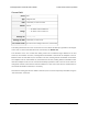
Tic
Control
Center
Advanced settings tab, Pin configuration box, RC
This byte contains most of the configuration of the RC pin, as described in Section 5.5.
If the pin function is set to “Default”, then the Tic will use the RC pin as an RC pulse input and measure
the durations of pulses received on the line.
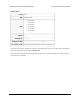
Note that the settings file has all of the RC configuration options on one line, but in the Tic’s EEPROM,
those settings are stored in multiple places: the RC pin configuration byte, the switch polarity map
byte, and the kill switch map byte.
Tic Stepper Motor Controller User’s Guide © 2001–2018 Pololu Corporation
6. Setting reference Page 101 of 150