
Data Sheet

9. Configuring Your RC Switch
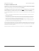
The RC switch has two user-settable configuration parameters, threshold and inversion, which are described in
Section 7. This section and the following sections explain how to set both parameters.
To configure the device, you will need to be able to connect and disconnect the two parts of the learning mode jumper.
This will be required at several points by the instructions in the following sections.
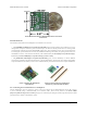
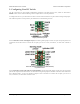
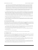
Pololu RC Switch with Digital
Output, labeled top view.
For the Pololu RC Switch with Digital Output, the learning mode jumper consists of a pair of exposed pads on the
component side of the board. To connect the two pads, you can use a wire, screwdriver, or some other conductive
tool.
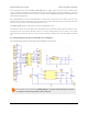
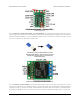
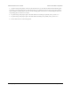
Pololu RC Switch with Small Low-Side MOSFET,
top labeled view.
For the Pololu RC Switch with Small Low-Side MOSFET, the learning mode jumper consists of a pair of exposed
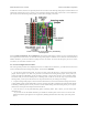
pads on the component side of the board. An alternate learning mode jumper is available on the other side of the board
and is labeled “LRN”; you can use whichever jumper is more convenient. To connect the two pads, you can use a
wire, screwdriver, or some other conductive tool.
Pololu RC Switch User’s Guide © 2001–2015 Pololu Corporation
9. Configuring Your RC Switch Page 31 of 35