
Data Sheet

8. Outputs and Indicator LED
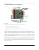
The OUT pin is an output that indicates whether the switch is active. The OUT pin is high whenever the integrated
MOSFET or relay is turned on. The Pololu 4-Channel RC Multiplexer does not have an OUT pin, but the same signal
could be accessed by soldering a wire to the board as described in Section 6.1.
The GOOD pin is an output that indicates whether the signal is valid (10–330 Hz pulse rate, 0.5–2.5 ms pulse width).
When the GOOD pin is low, it means the signal is invalid. In that situation, the OUT pin will also be low. The RC
multiplexer does not have a GOOD pin, but it does have an inverted GOOD pin as described in Section 6.1.
The yellow indicator LED shows what state the device is in. There are four states the device can be in during normal
operation:
• If there is no input signal, the LED will blink with a 50% duty cycle and a period of 1 s. In this case, the OUT
and GOOD pins will be low.
• If the pulses are in the on position but the switch is not active because safe-start mode is active, the LED will
do a double-blink with a period of 1 s. In this case, the OUT pin will be low and the GOOD pin will be high.
• If the pulses are in the off position, the output will be off and the LED will do a brief blink once per second.
In this case, the OUT pin will be low and the GOOD pin will be high.
• If the pulses are in the on position and the output is on, the LED will be mostly on and blink off briefly once
per second. In this case, the OUT and GOOD pins will be high.
If the power supply voltage drops too low, the device will detect this and stop running. This is called a brown-out
reset. After the power supply voltage recovers (which could be a few milliseconds later), the device will suspend
normal operation briefly and do a special LED blink. The blink consists of a single blink followed by a double blink,
with a period of 7/8 s and three repetitions.
During learning mode, the LED exhibits several other types of blinking. These are documented in Section 9.
Pololu RC Switch User’s Guide © 2001–2015 Pololu Corporation
8. Outputs and Indicator LED Page 30 of 35