
Data Sheet
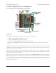
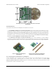

We recommend that you connect the SEL and M1–M4 inputs to a single “master” RC device, such as an RC receiver
or servo controller. The master device should have a power source that supplies power the RC multiplexer. The power
supplied by the master should be between 2.5 and 16 V and it must be capable of supplying the current that the servos
connected to the outputs draw.
We recommend that you connect the S1–S4 inputs to a single “slave” RC device, such as an RC receiver or servo
controller. The slave device will need a source of power. You can either connect the slave power directly to the slave
device or you can connect it to the GND/VS pin pair next to S1.
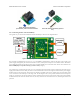
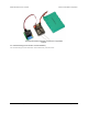
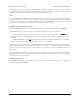
The OUT1–OUT4 outputs can be directly connected to standard RC servos.
The master RC device can use the SEL line to select which device controls the outputs. When the switch is active,
the signal received on S1 will be reflected on OUT1, so a device sending pulses to S1 can control a servo or ESC
connected to OUT1. When the switch is not active, OUT1 will reflect the input on M1. The same applies to channels
2–4.
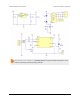
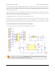
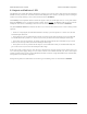
6.3. Schematic Diagram for the 4-Channel RC Servo Multiplexer
The schematic diagram of the 4-Channel RC Servo Multiplexer is shown below:
This schematic is also available as a printable pdf [https://www.pololu.com/file/download/pololu-4-channel-rc-
servo-multiplexer-schematic-diagram.pdf?file_id=0J701] (210k pdf).
Pololu RC Switch User’s Guide © 2001–2015 Pololu Corporation
6. Pololu 4-Channel RC Servo Multiplexer Page 27 of 35