
Data Sheet

Note that SEL is the only input that requires a valid RC servo signal (10–330 Hz pulse rate, 0.5–2.5 ms pulse width);
the master and slave inputs can be general digital signals. For example, you could use OUT4 to control the brightness
of a small (< 20 mA) LED by sending PWM signals to the inputs on S4 and M4.
Power
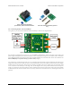
The power supplied by the master RC device should be between 2.5 and 16 V, and it must be capable of supplying
the current that the servos connected to the outputs draw. The power pins of the SEL, M1–M4, and OUT1–OUT4
channels are all connected to the same VM rail, and the board draws its power from those pins. The power pins of the
S1–S4 inputs are connected to each other on the VS rail but are not used by the board.
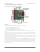
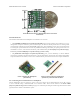
Additional outputs and indicator LED
The yellow indicator LED indicates what state the switch is in. The LED behavior is described in Section 8.
The FAILMODE jumper consists of two pins that might be individually useful to advanced users:
• The FAILMODE pin with the octagonal pad (the one closer to the edge of the board) is the GOOD output.
This output is low when signal on the SEL input is valid, and high when the signal on the SEL input is invalid
or missing.
• The other FAILMODE pin is the EN input. This input is pulled low by default. When this input is driven high,
it disables all of the output channels, causing them to go low (0 V) and stay low.
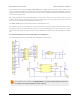
The RC multiplexer has an internal signal named OUT that indicates whether the switch is activated or not. The OUT
signal is high when the switch is active and is low otherwise. This signal is not accessible on any through-hole pin
but you can access it by finding the 16-pin chip and soldering a wire to the pin 1, which is the pin that is closest to the
OUT1 channel.
When high, all the output signals on the device will output a voltage approximately equal to 5 V or VM, whichever is
lower. When low, these outputs will be at 0 V (ground). These outputs do not have resistors in series with them. Each
output can source or sink up to 25 mA.
Configuration interface
The learning mode jumper can be used to get the device into learning mode and configure it. The configuration
procedure is described in Section 9.
Pololu RC Switch User’s Guide © 2001–2015 Pololu Corporation
6. Pololu 4-Channel RC Servo Multiplexer Page 25 of 35