
Data Sheet

6. Pololu 4-Channel RC Servo Multiplexer
6.1. Components of the 4-Channel RC Servo Multiplexer
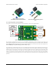
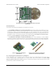
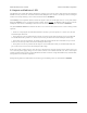
Pololu 4-Channel RC Servo Multiplexer (Assembled),
labeled pinout.
RC interface
The Pololu 4-Channel RC Servo Multiplexer has a total of 13 RC servo channels:
• The four inputs M1–M4 are called the master inputs.
• The four inputs S1–S4 are called the slave inputs.
• The four outputs OUT1–OUT4 are the main outputs of the device.
• The signal on the SEL input channel determines whether the outputs map to the master inputs or the slave
inputs.
This guide uses the terms active, activated, and activation to refer to the active state of the switch. For the RC
multiplexer, active means that the outputs reflect the slave inputs. By default, the switch will not be active and the
master inputs will show up on the outputs.
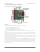
Each servo channel consists of three pins: GND, power, and signal. As shown in the diagram above, the GND
(ground) pins are on the edge of the board and the power pins are in the middle between GND and signal. All ground
pins are internally connected on the board.
When the RC signal on the SEL channel is lost or invalid, the optional FAILMODE jumper determines the output
behavior. If the jumper is left off, the master inputs will be in control. If the jumper is connected, the output channels
go low and stay low for as long as the signal on the SEL channel remains invalid. For many servos and electronic
speed controls (ESCs), a constant low on the signal line will turn them off, which might be desirable if the control
signals are known to be bad.
Pololu RC Switch User’s Guide © 2001–2015 Pololu Corporation
6. Pololu 4-Channel RC Servo Multiplexer Page 24 of 35