
Data Sheet
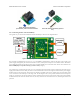


Pololu RC Switch with Relay
(Assembled) with included hardware.
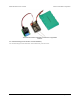
Pololu RC Switch with Relay (Partial
Kit).
5.2. Connecting the RC Switch with Relay
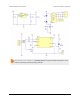
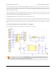
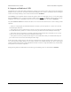
The typical way to connect the Pololu RC Switch with Relay is shown in the diagram below:
Typical wiring diagram for the Pololu RC Switch with Relay.
We generally recommend that you use a 4- or 5-cell NiMH or NiCD battery pack for the logic power supply. The
power supply will typically be connected to the RC receiver, which passes the power on to the RC switch. The switch
can be plugged directly into the RC receiver using a Female-Female servo extension cable. These can be found in our
Servo Cables [https://www.pololu.com/category/112/servo-cables] category.
One typical way of connecting the relay is to put it between the load and the positive terminal of the load’s power
supply. The load is the device that you want to control with the RC switch. The negative terminal of the power supply
should connect to the other side of the load. The negative terminal of the power supply does not necessarily need
to be connected to the GND pin of the logic side. In the diagram above, the positive terminal of the load power
supply is connected to the NO pin and the positive terminal of the load is connected to COM. They will normally
be disconnected, but when the switch turns on, the relay will activate and connect the two, allowing the load to be
powered.
Pololu RC Switch User’s Guide © 2001–2015 Pololu Corporation
5. RC Switch with Relay Page 21 of 35