
Data Sheet

These pins are electrically isolated from the logic side of the board and are routed on the PCB with a minimum
clearance of 60 mils (1.5 mm) from other copper and from the board edges, though manufacturing variations in the
board edges can make those distances slightly lower.
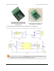
In most applications, the current and voltage ratings for the module will match the ratings of the relay used. Maximum
current, maximum voltage, and life expectancy are interdependent; we therefore recommend careful examination
of your relay’s datasheet. If you are using the included relay, please refer to the Omron G5LE-14-DC5 datasheet
[https://www.pololu.com/file/download/G5LE.pdf?file_id=0J619] (1MB pdf) for information.
Warning: The RC Switch with Relay is not designed to or certified for any particular high-voltage safety
standard. Working with voltages above 30 V can be extremely dangerous and should only be attempted by
qualified individuals with appropriate equipment and protective gear.
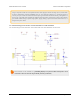
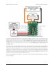
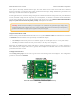
Outputs and indicator LED
The RC switch provides feedback about what state it is in via a yellow indicator LED. The LED behavior is described
in Section 8. Status information is also provided by two additional outputs:
• The GOOD pin indicates the presence of a valid RC signal (10–330 Hz pulse rate, 0.5–2.5 ms pulse width).
• The OUT pin indicates whether the relay is activated (i.e. the relay coil is energized).
When high, the GOOD and OUT outputs will output a voltage approximately equal to 5 V or VRC, whichever is
lower. When low, these outputs will be at 0 V (ground). These outputs have 220 Ohm resistors in series with them to
protect them from short circuits.
Configuration interface
The learning mode jumper can be used to get the device into learning mode and configure it. The configuration
procedure is described in Section 9.
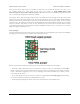
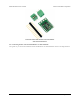
Pololu RC Switch with Relay carrier board, labeled top
view.
Pololu RC Switch User’s Guide © 2001–2015 Pololu Corporation
5. RC Switch with Relay Page 19 of 35