
Data Sheet

5. RC Switch with Relay
5.1. Components of the RC Switch with Relay
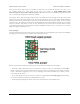
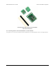
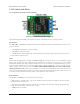
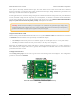
Pololu RC Switch with Relay, labeled top view.
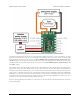
The Pololu RC Switch with Relay has five pins spaced 0.1″ apart that give access to its logic interface.
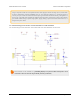
RC interface
The GND, VRC, and RC IN pins make up the switch’s RC interface and can be connected directly to an RC receiver
or servo controller:
• The GND pin is the ground or reference voltage.
• The VRC pin is the power input.
• The RC IN pin is the RC signal input. The switch measures the width of pulses on this line and uses that to
decide whether to activate or not.
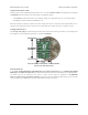
Power
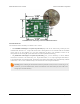
We generally recommend that you supply the GND and VRC pins with power from a 4- or 5-cell NiMH or NiCD
battery pack. Typically, the input voltage range will be limited by the properties of the relay coil. The included
Omron G5LE-14-DC5 relay requires an input voltage of at least 3.75 V to operate. At room temperature (23° C), the
relay can tolerate voltages up to 8.5 V, but this limit decreases at higher temperatures. At 85° C, the relay can only
tolerate voltages up to 6.5 V. You can see the Omron G5LE-14-DC5 datasheet [https://www.pololu.com/file/download/
G5LE.pdf?file_id=0J619] (1MB pdf) for more information. As a whole, the switch will draw about 100 mA when the
relay is on, but that current draw depends on the input voltage. The board itself can operate anywhere in the 2.5 to
16 V range, but the included Omron relay requires a more restrictive range of voltages.
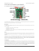
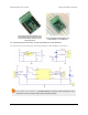
Relay interface
The NO, NC, and COM pins are connected directly to the relay.
• NO stands for “normally open”. This pin is normally disconnected from the COM pin, but they become
connected when the relay is active.
• NC stands for “normally connected”. The NC pin is normally connected to the COM pin through the relay,
but they become disconnected when the relay is active.
• COM stands for “common”.
Pololu RC Switch User’s Guide © 2001–2015 Pololu Corporation
5. RC Switch with Relay Page 18 of 35