
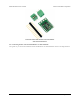
Data Sheet
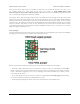
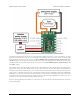
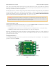

Typical wiring diagram for the Pololu RC Switch with Medium Low-Side MOSFET.
An onboard regulator allows the switch to be powered from voltages between 2.5 V and 16 V. However, for most
applications we recommend using a 4- or 5-cell NiMH or NiCD battery pack to power the switch. The battery pack
will typically be connected to an RC receiver or servo controller [https://www.pololu.com/category/102/maestro-usb-servo-
controllers], which passes the power on to the RC switch. The switch can be plugged directly into the RC receiver using
a Female-Female servo extension cable. These can be found in our Servo Cables [https://www.pololu.com/category/112/
servo-cables] category.
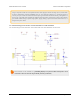
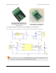
The negative side of your load supply should connect to the GND pad on the top-right side of the board, and the
negative side of the load itself should connect to the LOAD LOW pin. The four pins labeled LOAD HIGH are
internally connected and intended to give you convenient connection points for both your load and your load power
supply. There is a flyback (also known as a “freewheeling”) diode between the MOSFET output and LOAD HIGH,
which allows you to safely connect an inductive load such as a motor or relay. Alternatively, the positive side of the
load could be directly connected to the load supply off of the board. The board’s MOSFET can deliver up to 15 A
with VCC at 5 V and can handle load supply voltages up to 30 V.
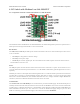
For lower power applications the smaller 0.1″-spaced pins can be used instead of the terminal block to connect the
load and load supply.
Pololu RC Switch User’s Guide © 2001–2015 Pololu Corporation
4. RC Switch with Medium Low-Side MOSFET Page 16 of 35