
Data Sheet
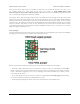
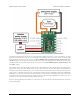
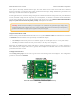

Outputs and indicator LED
The RC switch provides feedback about what state it is in via a yellow indicator LED. The LED behavior is described
in Section 8. Status information is also provided by two additional outputs:
• The GOOD pin indicates the presence of a valid RC signal (10–330 Hz pulse rate, 0.5–2.5 ms pulse width).
• The OUT pin indicates whether the MOSFET is on.
When these outputs are high they will be at the same voltage level as VCC. When low, these outputs will be at 0 V
(ground). These outputs do not have resistors in series with them. Each output can source or sink up to 25 mA.
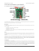
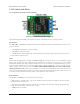
Configuration interface
The learning mode jumper on both the top and bottom of the board can be used to get the device into learning mode
and configure it. The configuration procedure is described in Section 9.
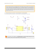
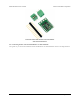
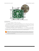
Pololu RC Switch with Medium Low-Side MOSFET,
bottom view with dimensions.
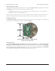
Included hardware
A 12-pin 0.1″ straight breakaway male header [https://www.pololu.com/product/965] and two 3.5 mm 2-pin terminal
blocks [https://www.pololu.com/product/2446] are included with the Pololu RC Switch with Medium Low-Side MOSFET.
The header pins can be soldered in and used to connect the RC switch to perfboards or breadboards
[https://www.pololu.com/category/28/solderless-breadboards]. Please note that the included terminal blocks are only rated for
10 A; for higher power applications, use thick wires soldered directly to the board.
Pololu RC Switch User’s Guide © 2001–2015 Pololu Corporation
4. RC Switch with Medium Low-Side MOSFET Page 14 of 35