
Data Sheet

4. RC Switch with Medium Low-Side MOSFET
4.1. Components of the RC Switch with Medium Low-Side MOSFET
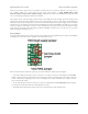
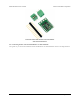
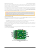
Pololu RC Switch with Medium Low-Side MOSFET, labeled top
view.
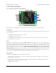
The Pololu RC Switch with Medium Low-Side MOSFET has 12 smaller through holes spaced 0.1″ apart that fit 0.1″
header pins and four larger holes that fit 3.5 mm screw terminals.
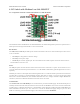
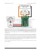
RC interface
The GND, VIN, and RC IN pins make up the switch’s RC interface and can be connected directly to an RC receiver
or servo controller:
• The GND pin is the ground or reference voltage.
• The VIN pin is the power input.
• The RC IN pin is the RC signal input. The switch measures the width of pulses on this line and uses that to
decide whether to activate or not.
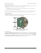
Power
The VIN pins power the basic functions of the board and need to be connected to a power source between 2.5 V to
16 V. This allows the board to be powered from a 4- or 5-cell NiMH or NiCD battery pack through an RC receiver or
separately.
The VCC pin connects to the output of the onboard regulator and is 5 V when the board is powered with a source that
is greater than or equal to 5 V and approximately equal to VIN when it is below 5 V. VCC is also the gate voltage
that is used to turn the MOSFET on, so it should be noted that lower VCC voltages will lead to higher MOSFET on
resistances, which in turn limits the maximum current the device can switch.
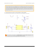
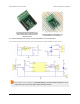
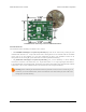
Load interface
The LOAD LOW and LOAD HIGH pins are connections for your load and load supply. The LOAD LOW pins are
normally disconnected from GND, but when the switch activates the MOSFET turns on and connects LOAD LOW
to GND. There is a flyback (also known as a “freewheeling”) diode between LOAD LOW and LOAD HIGH. The
board’s MOSFET can deliver up to 15 A with VCC at 5 V and can handle load supply voltages up to 30 V. More
details on connecting your load and load supply to the switch can be found in Section 4.2.
Pololu RC Switch User’s Guide © 2001–2015 Pololu Corporation
4. RC Switch with Medium Low-Side MOSFET Page 13 of 35