
Data Sheet
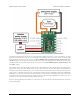
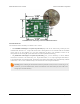

Large or capacitive loads can cause problems if the same supply is used for the logic (VCC) and the load.
In such a configuration, when the MOSFET turns on, VCC might drop below 2.5 V, causing the board to
reset. If you try to activate the switch but the board just goes into safe-start mode instead, you might have a
power issue, especially if the problem only happens when the load is connected. If you have this problem,
you should consider using a separate logic power supply, adding a capacitor between GND and VCC, or
using shorter power leads.
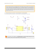
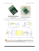
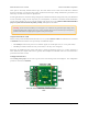
3.3. Schematic Diagram for the RC Switch with Small Low-Side MOSFET
The schematic diagram of the Pololu RC Switch with Small Low-Side MOSFET is shown below:
This schematic is also available as a printable pdf [https://www.pololu.com/file/download/pololu-rc-switch-
with-small-low-side-mosfet-schematic-diagram.PDF?file_id=0J699] (143k PDF).
Pololu RC Switch User’s Guide © 2001–2015 Pololu Corporation
3. RC Switch with Small Low-Side MOSFET Page 12 of 35