
Data Sheet

3. Pinout and components
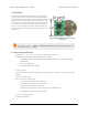
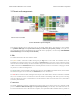
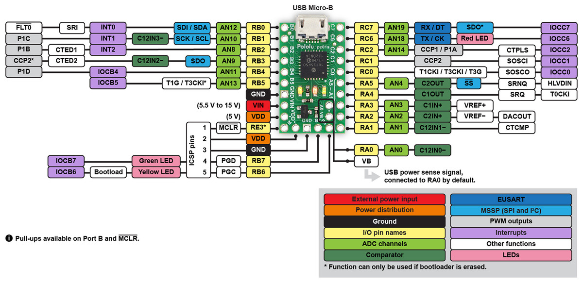
P-Star 25K50 Micro pinout diagram.
This diagram identifies the I/O and power pins on the P-Star 25K50 Micro. The diagram is also available
as a printable PDF [https://www.pololu.com/file/download/p-star-25K50-micro-pinout.pdf?file_id=0J799] (161k pdf). For
more information about the PIC18F25K50 microcontroller and its peripherals, see Microchip’s PIC18F25K50
documentation [http://www.microchip.com/PIC18F25K50].
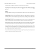
LEDs
The P-Star 25K50 Micro has three indicator LEDs.
The yellow LED is connected to RB6. Driving this pin high turns on the LED. In bootloader mode, the
bootloader drives this line high to turn on the LED (see Section 6.4) but never drives it low. If this line is high
when the microcontroller starts up, the microcontroller will go into bootloader mode. A button can be connected
to RB6 as described in Section 5.2. RB6 has an onboard pull-down resistor to ensure that its voltage goes all the
way down to 0 V when not being driven.
The green LED is connected to RB7, and lights when the pin is driven high. In bootloader mode, the bootloader
drives this line high to turn on the LED (see Section 6.4) but never drives it low.
The red LED is connected to RC6, and lights when the pin is driven low. RC6 is the microcontroller’s serial TX
line, so the red LED serves as an indicator for when the board is transmitting serial data. If you are not using
serial, the LED can be used as a normal LED. To avoid interference with connected serial devices, this LED is
not used by the bootloader.
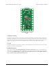
Connectors
The P-Star 25K50 Micro includes a USB Micro-B connector that can be used to connect to a computer’s USB
port via a USB A to Micro-B cable [https://www.pololu.com/product/2072] (not included). The USB connection can
be used to transmit and receive data from the computer, and a preloaded USB bootloader makes it possible to
Pololu P-Star 25K50 Micro User’s Guide © 2001–2017 Pololu Corporation
3. Pinout and components Page 6 of 38