
Data Sheet

USB Configured state. If the device has not reached the Configured state, the green LED will blink on and off
with a 50% duty cycle and a period of about 1.4 seconds. If the device has reached the Configured state, then it
will do a double-blink every 1.4 seconds.
The yellow LED is usually on solid, but it will blink quickly whenever a USB command is received.
If USB is not connected or the USB connection is in suspend mode, the bootloader will briefly blink the green
LED about once per second, and the yellow LED will be off.
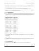
6.5. Configuration bits
The PIC18F25K50 has several configuration bits in flash memory. For the P-Star, the values of those
configuration bits are shown in the table below. These configuration bits cannot be changed by the bootloader or
an application loaded by the bootloader; you will need to use an external programmer and erase the bootloader
if you want to change any of them.
Register name Hex value Binary value
CONFIG1L 0x23 00100011
CONFIG1H 0x02 00000010
CONFIG2L 0x02 00000010
CONFIG2H 0x22 00100010
CONFIG3H 0xD3 11010011
CONFIG4L 0x85 10000101
CONFIG5L 0x0E 00001110
CONFIG5H 0xC0 11000000
CONFIG6L 0x0E 00001110
CONFIG6H 0x80 10000000
CONFIG7L 0x0E 00001110
CONFIG7H 0x40 01000000
Full documentation of these settings can be found in the PIC18F25K50 datasheet, and some of the settings are
discussed below.
Instruction set
The PIC18 extended instruction set is disabled, so the microcontroller uses the legacy instruction set. The legacy
instruction set is the only instruction set supported by the XC8 compiler, but if you use a different compiler then
you should make sure it supports the legacy instruction set and is configured to use it.
I/O pin configuration
The MCLRE bit is set to 1, so the MCLR pin is used as a reset pin and not a generic digital input.
Pololu P-Star 25K50 Micro User’s Guide © 2001–2017 Pololu Corporation
6. The P-Star 25K50 Bootloader Page 24 of 38