
Data Sheet
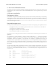
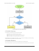
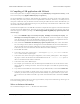

The startup logic for the P-Star USB bootloader.
6.3. Bootloader I/O pin usage
The bootloader uses the following I/O pins of the microcontroller:
• D- and D+ are used to communicate with the USB host.
• RB6 is driven high to turn on the yellow LED, but never driven low.
• RB7 is driven high to turn on the green LED, but never driven low.
The bootloader does not use RA0 to detect VBUS, so you can use RA0 for something else without interfering
with the bootloader. The bootloader does not use the red LED.
6.4. Bootloader LED behavior
This section documents the behavior of the P-Star’s LEDs while it is in bootloader mode.
If an active USB connection is present, the green LED will blink to indicate whether the device has reached the
Pololu P-Star 25K50 Micro User’s Guide © 2001–2017 Pololu Corporation
6. The P-Star 25K50 Bootloader Page 23 of 38