
Data Sheet


6. The P-Star 25K50 Bootloader
The P-Star comes with a proprietary bootloader developed by Pololu that uses a native USB protocol. The
bootloader allows you to read and write the flash and EEPROM memories of the chip without using an external
programmer.
6.1. Memory organization
Flash memory sections
The bootloader occupies the first 8 KB (8192 bytes) of the PIC microcontroller’s flash memory. The remaining
24 KB of flash is available for the application. The bootloader places no restrictions on what data can be written
to the application section. However, the bootloader will consider the application to be invalid and not allow any
code in the application section to run if the first word of the application section (at address 0x2000) is 0xFFFF,
which would correspond to a NOP.
Entry and interrupt vectors
The entry vector and interrupt vectors are remapped by the bootloader to the beginning of the application section:
• The application’s entry vector should be placed at 0x2000. This is the location where code will start
executing when the application is started.
• The high-priority interrupt vector should be at 0x2008.
• The low-priority interrupt vector should be at 0x2018.
The interrupt vectors can be ignored and those locations can hold normal code if interrupts are not enabled in the
application.
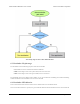
The application can start the bootloader by jumping to address 0x0004 using a goto instruction. This method
of starting the bootloader does not involve a reset, so the state of the microcontroller matters and certain
configurations could cause problems for the bootloader. For example, an application that changes the
configuration of the system oscillators will most likely have to revert its changes before starting the bootloader.
Also, an application that uses USB should disable the USB module by clearing USBEN and then wait for at
least 100 ms before starting the bootloader, in order to give the computer time to detect that the application has
disconnected.
The code below is PIC assembly code that shows how these vectors are defined in the bootloader. The two CPU
interrupt vectors (0x0008 and 0x0018) each have a goto instruction that jumps directly to the user application.
The two entry vectors (0x0000 and 0x0004) each have goto instructions that jump to the appropriate part of the
bootloader code.
org 0x0000 ; CPU reset vector
goto powerup ; Start app or bootloader
org 0x0004 ; Bootloader launch vector
goto powerupBootloader ; Start bootloader
org 0x0008 ; CPU high-priority interrupt vector
goto 0x2008 ; Jump to the application's ISR
org 0x0018 ; CPU low-priority interrupt vector
goto 0x2018 ; Jump to the application's ISR
Pololu P-Star 25K50 Micro User’s Guide © 2001–2017 Pololu Corporation
6. The P-Star 25K50 Bootloader Page 21 of 38