
Data Sheet
• 3 additional I/O pins available in other locations
• 13 pins can be configured as analog inputs
• 2 PWM output signals (one of which can be sent to four different pins)
• 5-bit digital-to-analog converter (DAC) output
Three user-controllable LEDs
USB micro-B connector
Can be powered from USB or external source regulated to 5 V by onboard regulator
Operating voltage: 5.5 V to 15 V
• Can operate down to 3.8 V with decreased logic voltage
Reverse-voltage protection on external power input
PTC fuse on VBUS supply
Ships with a proprietary USB bootloader developed by pololu for the p-star
Bootloader is usable from windows, linux, and mac OS X with open source software
No external programmer required
Compatible with standard microchip compilers, development tools, and programmers
Comprehensive user’s guide
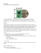
This diagram identifies the I/O and power pins on the P-Star 25K50 Micro. The diagram is also
available as a printable PDF (161k pdf). For more information about the PIC18F25K50 microcontroller
and its peripherals, see microchip’s PIC18F25K50 documentation.
Included hardware
Two 1×10-pin breakaway 0.1" male headers and one 1×6-pin breakaway 0.1" male header are included
with the P-Star 25K50 micro. These header pins can be soldered in to use the board with perfboards,
breadboards, or 0.1" female connectors.