
Data Sheet


MP6500 – 35V, 2.5A, STEP MOTOR DRIVER W/ INTERNAL CURRENT SENSE
MP6500 Rev. 1.0 www.MonolithicPower.com 10
6/22/2017 MPS Proprietary Information. Patent Protected. Unauthorized Photocopy and Duplication Prohibited.
© 2017 MPS. All Rights Reserved.
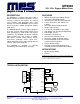
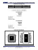
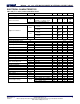
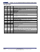
PIN FUNCTIONS
Pin #
QFN
Pin #
TSSOP
Name
Description
1
11
DIR
Direction input. DIR has an internal pull-down resistor.
2
12
nFAULT
Fault indication. nFAULT is an open-drain output. Drive nFAULT to logic low
when in a fault condition (OCP, OTP, OVP).
3
13
ISET
Current set programming. A resistor from ISET to ground sets the current
through the motor.
4
14
AGND
Analog ground.
5
15
ROSC
Constant off-time programming. A resistor from ROSC to ground sets the
PWM off time.
6
16
MS2
Mode selection. MS1 and MS2 set the step mode (full, 1/2, 1/4, or 1/8 step).
MS1 and MS2 have an internal pull-down resistor.
7
18
MS1
8, 12,
20, 24,
EP
6, 10,
19, 23,
EP
GND
Power ground.
9
20
BOUT1
Bridge B output terminal 1.
10, 22
8, 21
VIN
Input supply voltage. Both VIN pins must be connected to the same supply.
Decouple VIN to ground with a minimum 100nF ceramic capacitor.
11
22
BOUT2
Bridge B output terminal 2.
13
24
STEP
Step input. The rising edge sequences the translator and advances the motor
by one increment. STEP has an internal pull-down resistor.
14
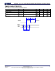
25
VCP
Charge pump output. VCP requires a 1µF, 16V, ceramic capacitor to VIN.
15
28
CP2
Charge pump capacitor. Connect a 100nF ceramic capacitor rated for the VIN
voltage between these terminals.
16
1
CP1
17
2
VG
Low-side MOSFETs gate drive voltage. VG requires a 220nF, 16V, ceramic
capacitor to ground.
-
3, 17,
26, 27
NC
No connection.
18
4
nENBL
Enable input. Drive nENBL to logic high to disable the bridge outputs and
translator operation. Drive nENBL to logic low to enable the bridge outputs and
translator operation. nENBL has an internal pull-down resistor.
19
5
nSLEEP
Sleep mode input. Drive nSLEEP to logic high to enable normal operation.
nSLEEP has an internal pull-down resistor .
21
7
AOUT2
Bridge A output terminal 2.
23
9
AOUT1
Bridge A output terminal 1.