Pololu Maestro Servo Controller User's Guide © 2001–2014 Pololu Corporation Pololu Maestro Servo Controller User's Guide http://www.pololu.
Pololu Maestro Servo Controller User's Guide 1. Overview . . . . . . . . . . . . . . . . . . . . . . . . . 1.a. Micro Maestro Pinout and Components . . . . . 1.b. Mini Maestro Pinout and Components . . . . . . 1.c. Indicator LEDs . . . . . . . . . . . . . . . . . . 1.d. Supported Operating Systems . . . . . . . . . . . 2. Contacting Pololu . . . . . . . . . . . . . . . . . . . . . 3. Getting Started . . . . . . . . . . . . . . . . . . . . . . 3.a. Installing Windows Drivers and Software . . . . 3.b.
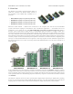
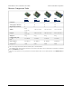
Pololu Maestro Servo Controller User's Guide © 2001–2014 Pololu Corporation 1. Overview The Maestros are Pololu’s second-generation family of USB servo controllers. The Maestro family consists of four controllers, each available fully assembled or as a partial kit: • Micro Maestro 6 [http://www.pololu.com/product/1350] • Mini Maestro 12 [http://www.pololu.com/product/1352] • Mini Maestro 18 [http://www.pololu.com/product/1354] • Mini Maestro 24 [http://www.pololu.
Pololu Maestro Servo Controller User's Guide A USB A to mini-B cable computer. 1. Overview [http://www.pololu.
Pololu Maestro Servo Controller User's Guide © 2001–2014 Pololu Corporation Features • Three control methods: USB, TTL (5 V) serial, and internal scripting • 0.25μs output pulse width resolution (corresponds to approximately 0.
Pololu Maestro Servo Controller User's Guide © 2001–2014 Pololu Corporation Maestro Comparison Table Micro Maestro Mini Maestro 12 Mini Maestro 18 Mini Maestro 24 Channels: 6 12 18 24 Analog input channels: 6 12 12 12 Digital input channels: 0 0 6 12 Width: 0.85" (2.16 cm) 1.10" (2.79 cm) 1.10" (2.79 cm) 1.10" (2.79 cm) Length: 1.20" (3.05 cm) 1.42" (3.61 cm) 1.80" (4.57 cm) 2.30" (5.84 cm) Weight(1): 3.0 g 4.2 g 4.9 g 6.
Pololu Maestro Servo Controller User's Guide © 2001–2014 Pololu Corporation Application Examples • Serial servo controller for multi-servo projects (e.g. robot arms, animatronics, fun-house displays) based on microcontroller boards such as the BASIC Stamp, Orangutan robot controllers [http://www.pololu.com/category/8/robot-controllers], or Arduino platforms • Computer-based servo control over USB port • Computer interface for sensors and other electronics: ◦ Read a gyro or accelerometer [http://www.
Pololu Maestro Servo Controller User's Guide © 2001–2014 Pololu Corporation can also be used to send commands to the servo controller, get information about the servo controller’s current state, and send and receive TTL serial bytes on the TX and RX lines. The processor and the servos can have separate power supplies. Processor power must come either from USB or from an external 5–16V power supply connected to the VIN and GND inputs.
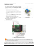
Pololu Maestro Servo Controller User's Guide © 2001–2014 Pololu Corporation Micro Maestro 6-channel USB servo controller bottom view with quarter for size reference. The dimensions of the Micro Maestro PCB are 1.2″ × 0.85″. The mounting holes have a diameter of 0.086″and are intended for #2 or M2 screws. The vertical and horizontal distances between the two mounting holes are 0.65″ and 0.575″. The Micro Maestro weighs 3.0 g (0.11 oz) without header pins. 1.b.
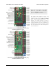
Pololu Maestro Servo Controller User's Guide © 2001–2014 Pololu Corporation Note: This section applies to the Mini Maestro 12, 18, and 24 servo controllers. Please see Section 1.a for Micro Maestro pinout and component information. The Pololu Mini Maestro 12-,18-, and 24-channel servo controllers can connect to a computer’s USB port via a USB A to mini-B cable [http://www.pololu.com/product/130] (not included). The USB connection is used to configure the servo controller.
Pololu Maestro Servo Controller User's Guide © 2001–2014 Pololu Corporation The processor and the servos can have separate power supplies. Processor power must come either from USB or from an external 5–16V power supply connected to the VIN and GND inputs on the left side of the board. It is safe to have an external power supply connected at the same time that USB is connected; in that case the processor will be powered from the external supply.
Pololu Maestro Servo Controller User's Guide © 2001–2014 Pololu Corporation The RST pin can be driven low to reset the Maestro’s microcontroller, but this should not be necessary for typical applications. The line is internally pulled high, so it is safe to leave this pin unconnected. Driving RST low is roughly equivalent to powering off the Maestro; it will not reset any of the configuration parameters stored in non-volatile memory.
Pololu Maestro Servo Controller User's Guide © 2001–2014 Pololu Corporation be controlled by the user script; the red LED will be on if there is an error or if the script command for turning it on was run. • The yellow status LED indicates the control status. When the Maestro is in auto-baud detect mode (the default) and has not yet detected the baud rate, the yellow LED will blink slowly. During this time the Maestro does not transmit any servo pulses.
Pololu Maestro Servo Controller User's Guide © 2001–2014 Pololu Corporation 2. Contacting Pololu You can check the product page of your particular Maestro model for additional information. We would be delighted to hear from you about any of your projects and about your experience with the Maestro. You can contact us [http://www.pololu.com/contact] directly or post on our forum [http://forum.pololu.com/].
Pololu Maestro Servo Controller User's Guide © 2001–2014 Pololu Corporation 3. Getting Started 3.a. Installing Windows Drivers and Software If you are using Windows XP, you will need to have Service Pack 3 [http://www.microsoft.com/downloads/ details.aspx?FamilyId=68C48DAD-BC34-40BE-8D85-6BB4F56F5110] installed before installing the drivers for the Maestro. See below for details. Before you connect your Maestro to a computer running Microsoft Windows, you should install its drivers: 1.
Pololu Maestro Servo Controller User's Guide © 2001–2014 Pololu Corporation 7. On the second screen of the “Found New Hardware Wizard”, select “Install the software automatically” and click “Next”. 3.
Pololu Maestro Servo Controller User's Guide © 2001–2014 Pololu Corporation 8. Windows XP will warn you again that the driver has not been tested by Microsoft and recommend that you stop the installation. Click “Continue Anyway”. 9. When you have finished the “Found New Hardware Wizard”, click “Finish”. After that, another wizard will pop up. You will see a total of three wizards when plugging in the Maestro. Follow steps 6-9 for each wizard. 3.
Pololu Maestro Servo Controller User's Guide © 2001–2014 Pololu Corporation If you use Windows XP and experience problems installing or using the serial port drivers, the cause of your problems might be a bug in older versions of Microsoft’s usb-to-serial driver usbser.sys. Versions of this driver prior to version 5.1.2600.2930 will not work with the Maestro. You can check what version of this driver you have by looking in the “Details” tab of the “Properties” window for usbser.
Pololu Maestro Servo Controller User's Guide © 2001–2014 Pololu Corporation Windows 7 device manager showing the Micro Maestro 6-channel USB servo controller. Windows XP device manager showing the Micro Maestro 6-channel USB servo controller. Some software will not allow connection to higher COM port numbers. If you need to change the COM port number assigned to your USB device, you can do so using the Device Manager.
Pololu Maestro Servo Controller User's Guide © 2001–2014 Pololu Corporation 3.b. Installing Linux Drivers and Software The Maestro Control Center running in Ubuntu Linux. You can download the Maestro Control Center and the Maestro command-line utility (UscCmd) for Linux here: • Maestro Servo Controller (112k gz) Linux Software [http://www.pololu.com/file/download/maestro- linux-100507.tar.gz?file_id=0J315] Unzip the tar/gzip archive by running “tar -xzvf” followed by the name of the file.
Pololu Maestro Servo Controller User's Guide © 2001–2014 Pololu Corporation • The 8-bit neutral point is 1500 μs and the 8-bit range is 476.25 μs. • On startup or error, the servos turn off (no pulses are sent). • On startup, there are no speed or acceleration limits, but you can set speed and acceleration limits using serial commands. • The servo period is 20 ms (each servo receives a pulse every 20 ms). • The user script is empty. 3.
Pololu Maestro Servo Controller User's Guide © 2001–2014 Pololu Corporation 4. Using the Maestro Control Center The Maestro’s USB interface provides access to all configuration options as well as support for real-time control, feedback, and debugging. The Maestro Control Center is a graphical tool that makes it easy for you to use the USB interface; for almost any project, you will want to start by using the control center to set up and test your Maestro.
Pololu Maestro Servo Controller User's Guide © 2001–2014 Pololu Corporation The “Speed” and “Acceleration” inputs allow the speed and acceleration of individual servo channels to be adjusted in real time. The default values are specified in the Settings tab, but it can be useful to adjust them here for fine-tuning. All of the controls on this tab always display the current values as reported by the Maestro itself, so they are useful for monitoring the actions caused by another program or device.
Pololu Maestro Servo Controller User's Guide © 2001–2014 Pololu Corporation 4.b. Errors The Errors tab in the Maestro Control Center. The Errors tab indicates problems that the Maestro has detected while running, either communications errors or errors generated by bugs in a script. Each error corresponds to a bit in the two-byte error register. The red LED will be on as long as any of the bits in the error register are set to 1 (it can also be turned on by the led_on script command).
Pololu Maestro Servo Controller User's Guide © 2001–2014 Pololu Corporation • Serial CRC error (bit 3) This error occurs when the Maestro is running in CRC-enabled mode and the cyclic redundancy check (CRC) byte at the end of the command packet does not match what the Maestro has computed as that packet’s CRC (Section 5.d). In such a case, the Maestro ignores the command packet and generates a CRC error.
Pololu Maestro Servo Controller User's Guide © 2001–2014 Pololu Corporation 4.c. Sequencer The Sequence tab in the Maestro Control Center. The Sequence tab allows simple motion sequences to be created and played back on the Maestro. A sequence is simply a list of “frames” specifying the positions of each of the servos and a duration (in milliseconds) for each frame. Sequences are stored in the registry of the computer where the sequence was created.
Pololu Maestro Servo Controller User's Guide © 2001–2014 Pololu Corporation The Sequence dropdown box along with the Rename, Delete, and New Sequence buttons allow you to create and manage multiple sequences. A sequence can also be used to create a script which is stored on the Maestro. There are two buttons for copying the sequence into the script: • Copy Sequence to Script sets the script to a looped version of the sequence.
Pololu Maestro Servo Controller User's Guide © 2001–2014 Pololu Corporation 4.d. Entering a Script The Script tab in the Maestro Control Center. The Script tab is where you enter a script to be loaded into the Maestro. For details on the Maestro scripting language, see Section 6. Once you have entered a script and clicked the “Apply Settings” button to load the script on to the device, there are a number of options available for testing and debugging your script on the Script tab.
Pololu Maestro Servo Controller User's Guide © 2001–2014 Pololu Corporation Examining the compiled code Click the “View Compiled Code” button to see the actual bytes that are created by each line of your script. This is available mostly as a tool for developers; if you are interested in the details of the bytecode used on the Maestro (for example, if you want to write your own compiler), please contact us [http://www.pololu.com/contact].
Pololu Maestro Servo Controller User's Guide © 2001–2014 Pololu Corporation • Output specifies that the channel should be used as a simple digital output. Instead of indicating a pulse width, the position value of the channel is used to control whether the output is low (0 V) or high (VCC). Specifically, the output is low unless the position value is greater than or equal to 1500.00 μs. Rate specifies the pulse rate for each Servo channel.
Pololu Maestro Servo Controller User's Guide Period (T) Rate T = 20 ms 50 Hz Speed units Acceleration units (0.25 μs)/(10 ms) (0.25 μs)/(10 ms)/(80 ms) T = 3–19 ms > 50 Hz (0.25 μs)/T T > 20 ms © 2001–2014 Pololu Corporation < 50 Hz (0.25 μs)/(T/2) (0.25 μs)/T/(8T) (0.25 μs)/(T/2)/(4T) Servos available is an advanced option for the Micro Maestro only specifying the number of channels that may be used to control servos.
Pololu Maestro Servo Controller User's Guide © 2001–2014 Pololu Corporation Upgrade Instructions You can determine the version of your Maestro’s firmware by running the Maestro Control Center, connecting to a Maestro, and looking at the firmware version number which is displayed in the upper left corner next to the “Connected to” drop-down box. If you do not already have the latest version (1.02), you can upgrade by following the instructions below: 1.
Pololu Maestro Servo Controller User's Guide © 2001–2014 Pololu Corporation 14. It will take a few seconds to erase the Maestro’s existing firmware and load the new firmware. Do not disconnect the Maestro during the upgrade. 15. Once the upgrade is complete, the Firmware Upgrade window will close, the Maestro will disconnect from your computer, and it will reappear. If there is only one Maestro plugged in to your computer, the Maestro Control Center will connect to it.
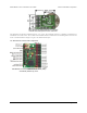
Pololu Maestro Servo Controller User's Guide © 2001–2014 Pololu Corporation Bootloader pads for the Mini Maestro 12-, 18-, or 24-Channel USB Servo Controller. 3. While the pads are shorted together, connect the Maestro to USB. Usually the easiest way to do this is to have one end of the USB cable already plugged into the Maestro, and connect the other end to the computer after you have shorted the pads. This might require a few tries.
Pololu Maestro Servo Controller User's Guide © 2001–2014 Pololu Corporation 5. Serial Interface 5.a. Serial Settings The Maestro has three different serial interfaces. First, it has the TX and RX lines, which allow the Maestro to send and receive non-inverted, TTL (0 – 5 V) serial bytes (Section 5.b). Secondly, the Maestro shows up as two virtual serial ports on a computer if it is connected via USB. One of these ports is called the Command Port and the other is called the TTL port.
Pololu Maestro Servo Controller User's Guide © 2001–2014 Pololu Corporation The Maestro can be configured to be in one of three basic serial modes: USB Dual Port: In this mode, the Command Port can be used to send commands to the Maestro and receive responses from it. The baud rate you set in your terminal program when opening the Command Port is irrelevant. The TTL Port can be used to send bytes on the TX line and receive bytes on the RX line.
Pololu Maestro Servo Controller User's Guide © 2001–2014 Pololu Corporation Mini SSC offset: This parameter determines which servo numbers the device will respond to in the Mini SSC protocol (see Section 5.e). Timeout: This parameter specifies the duration before which a Serial timeout error will occur. This error can be used as a safety measure to ensure that your servos and digital outputs go back to their default states whenever the software sending commands to the Maestro stops working.
Pololu Maestro Servo Controller User's Guide © 2001–2014 Pololu Corporation bytes per second is the baud rate divided by ten. At the Maestro’s maximum baud rate of 250,000 bits per second, the maximum realizable data rate, with a start bit coming immediately after the preceding byte’s stop bit, is 25,000 bytes per second. Whenever connecting devices, remember to wire the grounds together, and ensure that each device is properly powered.
Pololu Maestro Servo Controller User's Guide © 2001–2014 Pololu Corporation change. Any Maestro on the line whose device number matches the specified device number accepts the command that follows; all other Pololu devices ignore the command. The remaining bytes in the command packet are the same as the compact protocol command packet you would send, with one key difference: the compact protocol command byte is now a data byte for the command 0xAA and hence must have its most significant bit cleared.
Pololu Maestro Servo Controller User's Guide © 2001–2014 Pololu Corporation A detailed account of how cyclic redundancy checking works is beyond the scope of this document, but you can find a wealth of information using Wikipedia [http://en.wikipedia.org/wiki/Cyclic_redundancy_check]. The CRC computation is basically a carryless long division of a CRC “polynomial”, 0x91, into your message (expressed as a continuous stream of bits), where all you care about is the remainder.
Pololu Maestro Servo Controller User's Guide © 2001–2014 Pololu Corporation 1 0 1 0 0 0 1 0 | | | | 1 0 0 0 1 0 0 1 | | | | _______________ | | | | 1 0 1 0 1 1 0 0 | | 1 0 0 0 1 0 0 1 | | _______________ | | 1 0 0 1 0 1 0 0 1 0 0 0 1 0 0 1 _______________ 1 1 1 0 1 | | | | | | | | | 0 | | | | | | | | | 0 = 0x17 So the full command packet we would send with CRC enabled is: 0x83, 0x01, 0x17. 5.e.
Pololu Maestro Servo Controller User's Guide © 2001–2014 Pololu Corporation for that channel. Specifically, an 8-bit target of 127 corresponds to the neutral setting for that channel, while 0 or 254 correspond to the neutral setting minus or plus the range setting. These settings can be useful for calibrating motion without changing the program sending serial commands. The channel address is a value in the range 0–254.
Pololu Maestro Servo Controller User's Guide © 2001–2014 Pololu Corporation acceleration limit. An acceleration limit causes the speed of a servo to slowly ramp up until it reaches the maximum speed, then to ramp down again as position approaches target, resulting in a relatively smooth motion from one point to another. With acceleration and speed limits, only a few target settings are required to make natural-looking motions that would otherwise be quite complicated to produce.
Pololu Maestro Servo Controller User's Guide © 2001–2014 Pololu Corporation This command is used to determine whether the servo outputs have reached their targets or are still changing and will return 1 as long as there is at least one servo that is limited by a speed or acceleration setting still moving. Using this command together with the Set Target command, you can initiate several servo movements and wait for all the movements to finish before moving on to the next step of your program.
Pololu Maestro Servo Controller User's Guide © 2001–2014 Pololu Corporation Restart Script at Subroutine with Parameter Compact protocol: 0xA8, subroutine number, parameter low bits, parameter high bits Pololu protocol: 0xAA, device number, 0x28, subroutine number, parameter low bits, parameter high bits This command is just like the Restart Script at Subroutine command, except it loads a parameter on to the stack before starting the subroutine.
Pololu Maestro Servo Controller User's Guide © 2001–2014 Pololu Corporation Daisy chaining serial devices that have a TXIN input. Using a PC and a Maestro together as the master device The Maestro can enable a personal computer to be the master device. The Maestro must be connected to a PC with a USB cable and configured to be in either USB Dual Port or USB Chained serial mode.
Pololu Maestro Servo Controller User's Guide © 2001–2014 Pololu Corporation detected the baud rate, Pololu devices that expect a leading command byte of 0x80 will ignore command packets that start with 0xAA, and the Maestro will ignore command packets that start with 0x80. 5.h. Serial Example Code 5.h.1. Cross-platform C The example C code below works on Windows, Linux, and Mac OS X 10.7 or later.
Pololu Maestro Servo Controller User's Guide © 2001–2014 Pololu Corporation //const char * device = "/dev/cu.usbmodem00034567"; // Mac OS X int fd = open(device, O_RDWR | O_NOCTTY); if (fd == -1) { perror(device); return 1; } #ifndef _WIN32 struct termios options; tcgetattr(fd, &options); options.c_lflag &= ~(ECHO | ECHONL | ICANON | ISIG | IEXTEN); options.c_oflag &= ~(ONLCR | OCRNL); tcsetattr(fd, TCSANOW, &options); #endif int position = maestroGetPosition(fd, 0); printf("Current position is %d.
Pololu Maestro Servo Controller User's Guide } } © 2001–2014 Pololu Corporation putc(0xAA); putc(0x0C); putc(0x04); putc(0x00); putc(0x70); // Target position = 1500 us (typical neutral for servos) putc(0x2E); delay_ms(1000); 5.h.4. Bash script The following shell script sends Set Target commands to the Maestro’s virtual COM port. This script allows you to easily control a Maestro over USB from a computer running Linux or Mac OS X 10.7 (Lion) or later.
Pololu Maestro Servo Controller User's Guide © 2001–2014 Pololu Corporation 6. The Maestro Scripting Language A script is a sequence of commands that is executed by the Maestro. Commands can set servo targets, speeds, and accelerations, retrieve input values, and perform mathematical computations. Basic control structures – looping and conditionals – are available for use in making complicated scripts.
Pololu Maestro Servo Controller User's Guide © 2001–2014 Pololu Corporation 1 3 miNUS 4 # this is a comment! times with absolutely no effect on the compiled program. We generally use lower-case for commands and two or four spaces of indentation to indicate control structures and subroutines, but feel free to arrange your code to suit your personal style. Control structures The Maestro script language has several control structures, which allow arbitrarily complicated programs to be written.
Pololu Maestro Servo Controller User's Guide © 2001–2014 Pololu Corporation goto mylabel # ...any code here is skipped... 4000 1 servo mylabel: # the program continues here 4000 2 servo In this example, only servo 2 will get set to 4000, while servo 1 will be unchanged. Subroutines It can be useful to use the same sequence of commands many times throughout your program. Subroutines are used to make this easier and more space-efficient.
Pololu Maestro Servo Controller User's Guide © 2001–2014 Pololu Corporation Keywords stack effect keyword description BEGIN none marks the beginning of a loop ENDIF none ends a conditional block IF…ENDIF ELSE none begins the alternative block in IF…ELSE…ENDIF GOTO label none goes to the label label (define it with label:) IF -1 enters the conditional block if the argument is true (non-zero) in IF…ENDIF or IF…ELSE…ENDIF REPEAT none marks the end of a loop SUB name none defines a subro
Pololu Maestro Servo Controller User's Guide © 2001–2014 Pololu Corporation Stack commands command stack effect DEPTH +1 gets the number of numbers on the stack DROP -1 removes the top number from the stack DUP +1 duplicates the top number OVER +1 duplicates the number directly below the top, copying it onto the top PICK -1,+1 takes a number n between 0 and 63, then puts the nth number below the top onto the stack (0 PICK is equivalent to DUP) SWAP a,b → swaps the top two numbers b,a RO
Pololu Maestro Servo Controller User's Guide command C equivalent © 2001–2014 Pololu Corporation description BITWISE_AND & applies the boolean AND function to corresponding bits of the arguments BITWISE_OR | applies the boolean OR function to corresponding bits of the arguments BITWISE_XOR ^ applies the boolean XOR function to corresponding bits of the arguments DIVIDE / divides the arguments EQUALS = true if and only if the arguments are equal GREATER_THAN > true if and only if the first
Pololu Maestro Servo Controller User's Guide © 2001–2014 Pololu Corporation Servo, LED, and other output commands command stack effect description SPEED -2 sets the speed of the channel specified by the top element to the value in the second element (see Section 4.e) ACCELERATION -2 sets the acceleration of the channel specified by the top element to the value in the second element (see Section 4.
Pololu Maestro Servo Controller User's Guide © 2001–2014 Pololu Corporation led_on delay led_off delay repeat The numbers are placed on the stack at the beginning of the loop, then consumed later on in execution. Pay attention to the order of the numbers used here: the 900 goes on the stack first, and it is used last. A simple servo sequence The following script shows how to direct servo 0 to five different positions in a loop.
Pololu Maestro Servo Controller User's Guide © 2001–2014 Pololu Corporation Using the subroutine brings the script down to 31 bytes: 4 per position and 11 bytes of overhead for the loop and to define FRAME. We can go further: inspecting the compiled code shows that putting each number on the stack requires 3 bytes: one byte as a command, and two for the two-byte number. Numbers from 0 to 255 can be loaded onto the stack with just two bytes. Suppose in our application we do not need the full 0.
Pololu Maestro Servo Controller User's Guide © 2001–2014 Pololu Corporation just 1.1 bytes per frame. We could store a sequence containing 900 different positions in the memory of the Micro Maestro using this kind of script. Making smooth sequences with GET_MOVING_STATE Speed and acceleration settings can be used to make smooth motion sequences with the Maestro. However, a common problem is that you do not know how much you need to delay between frames to allow the servo to reach its final position.
Pololu Maestro Servo Controller User's Guide © 2001–2014 Pololu Corporation 8000 # go to 8000 for values 600-1023 endif endif 0 servo drop # remove the original copy of the pot value repeat The example above works, but when the potentiometer is close to 300 or 600, noise on the analog-to-digital conversion can cause the servo to jump randomly back and forth. A better way to do it is with hysteresis: # Set the servo to 4000, 6000, or 8000 depending on an analog input, with hysteresis.
Pololu Maestro Servo Controller User's Guide © 2001–2014 Pololu Corporation 0 get_position 500 less_than return # This subroutine uses the BUTTON subroutine above to wait for a button press, # including a small delay to eliminate noise or bounces on the input. sub wait_for_button_press wait_for_button_open_10ms wait_for_button_closed_10ms return # Wait for the button to be NOT pressed for at least 10 ms.
Pololu Maestro Servo Controller User's Guide © 2001–2014 Pololu Corporation button_c if sequence_c endif repeat # These subroutines each return 1 if the corresponding # button is pressed, and return 0 otherwise. # Currently button_a is assigned to channel 0, # button_b is assigned to channel 1, and # button_c is assigned to channel 2. # These channels must be configured as Inputs in the # Channel Settings tab.
Pololu Maestro Servo Controller User's Guide repeat drop return © 2001–2014 Pololu Corporation # remove the 0 from the stack and return It is easy to write subroutines for delays of hours, days, weeks, or whatever you want. Keep in mind, however, that the timer on the Micro Maestro is not as accurate as a stopwatch – these delays could easily be off by 1%.
Pololu Maestro Servo Controller User's Guide © 2001–2014 Pololu Corporation Serial output (Mini Maestro 12, 18, and 24 only) On the Mini Maestro 12, 18, and 24, a script can be used to send serial data out on the TTL-level serial port (TX). This means that the Maestro can control additional Maestros, allowing for large numbers of channels without a separate microcontroller. Here is a simple program that shows how a serial command can be used to control another Maestro.
Pololu Maestro Servo Controller User's Guide © 2001–2014 Pololu Corporation 7. Wiring Examples This section contains example wiring configurations for the Maestro that demonstrate the different ways it can be connected to your project. Although many of the pictures only show the Micro Maestro, the information in this section applies to all Maestros (unless otherwise noted). 7.a. Powering the Maestro There are several ways to power your Maestro’s processor and the servos it is controlling.
Pololu Maestro Servo Controller User's Guide © 2001–2014 Pololu Corporation One power supply If you connect a single power supply to VIN and the servo power terminal, then the Maestro’s processor and the servos will be powered from that supply. The supply must be within 5–16 V and be within the servos’ respective operating ranges and must be capable of supplying all the current that the servos will draw.
Pololu Maestro Servo Controller User's Guide © 2001–2014 Pololu Corporation Button or switch To connect a button or switch to the Maestro, you must first decide which channel you would like to use. In the Maestro Control Center, under the Channel Settings tab, change that channel to Input mode and click “Apply Settings”. Next, wire a pull-up resistor (1–100 kilo-ohms) between the signal line of that channel and 5 V so that the input is high (5 V) when the switch is open.
Pololu Maestro Servo Controller User's Guide © 2001–2014 Pololu Corporation LED To connect an LED to the Maestro, you should first decide which channel you would like to use. In the Maestro Control Center, under the Channel Settings tab, change that channel to Output mode and click “Apply Settings”. Next, connect the cathode of the LED to GND (any ground pad on the Maestro will suffice because they are all connected).
Pololu Maestro Servo Controller User's Guide © 2001–2014 Pololu Corporation 8. Writing PC Software to Control the Maestro There are two ways to write PC software to control the Maestro: the native USB interface and the virtual serial port. The native USB interface provides more features than the serial port, such as the ability to change configuration parameters and select the Maestro by its serial number. Also, the USB interface allows you to recover more easily from temporary disconnections.
Pololu Maestro Servo Controller User's Guide © 2001–2014 Pololu Corporation 9. Maestro Settings Limitations Mini Maestro serial baud rate limitations On the Mini Maestro 12, 18, and 24, the following baud rates should not be exceeded, or the processor may become overloaded, causing degraded performance. 10–100 Hz 111–250 Hz Serial mode: UART/USB chained* Serial mode: Dual-port 200 kbps 115.2 kbps 333 Hz 115.2 kbps 115.2 kbps 57.6 kbps 57.
Pololu Maestro Servo Controller User's Guide © 2001–2014 Pololu Corporation channels. If your settings happen to violate these restrictions, the servo period might increase and the units of speed and acceleration limits will change accordingly, but the operation of the Maestro will not be affected in any other way. For example, with a Mini Maestro 24 running at 250 Hz (a 4 ms period), you may use 12 servos with a range of 576–2880 μs and 6 servos with a range of 64–2880 μs.
Pololu Maestro Servo Controller User's Guide © 2001–2014 Pololu Corporation 10. Related Resources This section lists resources that might help you use the Maestro. Please note that these resources are of varying quality and most are not tested or supported by Pololu. Tutorials and example code • Sample Project: Simple Hexapod Walker [http://www.pololu.com/docs/0J42] • Pololu Mini Maestro and Arduino Tutorial [http://www.darrenfeetham.com/18ssc.html] • Obstacle avoider robot [http://forum.pololu.
Pololu Maestro Servo Controller User's Guide © 2001–2014 Pololu Corporation Accessories • Pololu Maestro Case [http://www.thingiverse.com/thing:6876]: This is a 3D design on Thingiverse for a case designed to fit the Micro Maestro 6-channel USB Servo Controller. 10.