
Data Sheet

DocID027112 Rev 4 37/50
LPS25HB Register description
50
the device. These values are factory trimmed and they are different for every device. They
allow correct behavior of the device and normally they should not be changed. The boot
process takes 2.2 msec. At the end of the boot process, the BOOT bit is set to ‘0’ automatically.
FIFO_MEAN_DEC bit is to decimate the output pressure to 1Hz with FIFO Mean mode.
When this bit is ‘1’, the output is decimated to 1 Hz as the moving average is being taken at
the rate of the ODR. Otherwise, averaged pressure data will be updated according to the
ODR defined.
SWRESET is the software reset bit. The device is reset to the power-on configuration after
SWRESET bit is set to '1'. The software reset process takes 4 μsec. When BOOT follows,
the recommended sequence is SWRESET first and then BOOT.
AUTOZERO, when set to ‘1’, the actual pressure output value is copied in REF_P_H (0Ah),
REF_P_L (09h) and REF_P_XL (08h). When this bit is enabled, the register content of
REF_P is subtracted from the pressure output value.
The ONE_SHOT bit is used to start a new conversion when the ODR[2,0] bits in
CTRL_REG1 (20h) are set to ‘000’. Writing a ‘1’ in ONE_SHOT triggers a single
measurement of pressure and temperature. Once the measurement is done, the
ONE_SHOT bit will self-clear, the new data are available in the output registers, and the
STATUS_REG bits are updated.
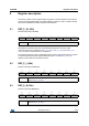
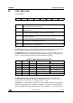
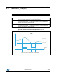
8.8 CTRL_REG3 (22h)
Interrupt control
76543210
INT_H_L PP_OD Reserved INT_S2 INT_S1
INT_H_L Interrupt active high, low. Default value: 0.
(0: active high; 1: active low)
PP_OD Push-pull/open drain selection on interrupt pads. Default value: 0.
(0: push-pull; 1: open drain)
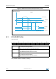
INT_S[2:1] Data signal on INT_DRDY pin control bits. Default value: 00.
Refer to Table 21.
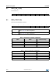
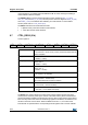
Table 21. Interrupt configurations
INT_S2 INT_S1 INT_DRDY pin configuration
0 0 Data signal (see CTRL_REG4 (23h))
0 1 Pressure high (P_high)
1 0 Pressure low (P_low)
1 1 Pressure low OR high