
Data Sheet

Application hints LPS25HB
22/50 DocID027112 Rev 4
5 Application hints
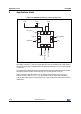
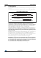
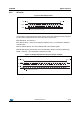
Figure 12. LPS25HB electrical connections (top view)
The device power supply must be provided through the VDD line; the power supply
decoupling capacitor C1 (100 nF) must be placed as near as possible to the supply pads of
the device. Depending on the application, an additional capacitor of 4.7 μF could be placed
on VDD line.
The functionality of the device and the measured data outputs are selectable and accessible
through the I²C/SPI interface. When using the I²C, CS must be tied to Vdd_IO.
All the voltage and ground supplies must be present at the same time to have proper
behavior of the IC (refer to Figure 12.). It is possible to remove VDD while maintaining
Vdd_IO without blocking the communication bus, in this condition the measurement chain is
powered off.
10
GND
89
354
7
6
1
2
Vdd_IO
SCL/SPC
SDA/SDI/SDO
SDO/SA0
VDD
INT_DRDY
CS
GND
C1
GND
Pin indicator