
Manual
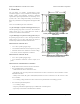


The jrk 21v3 ships with a 14×1 straight 0.100" male header strip [http://www.pololu.com/catalog/product/965] and
two 3.5mm, 2-pin terminal blocks. The jrk 12v12 ships with a 14×1 straight 0.100" male header strip
[http://www.pololu.com/catalog/product/965] and two 5mm, 2-pin terminal blocks [http://www.pololu.com/catalog/product/2440].
To provide maximum flexibility, none of these parts are soldered to the board.
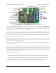
For the most compact installation, you can solder wires directly to the jrk pads themselves and skip using the included
hardware. The included hardware allows you to make less permanent connections. You can break the 14×1 header
strip into an 8×1 piece and two 3×1 pieces and solder these strips into the jrk’s I/O pads.
The three mounting holes are intended for use with #2 screws [http://www.pololu.com/catalog/category/101] (not included).
Note: A USB A to mini-B cable [http://www.pololu.com/catalog/product/130] (not included) is required to
connect this device to a computer.
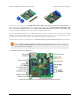
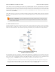
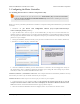
1.a. Module Pinout and Components
Pololu jrk 21v3 USB motor controller with feedback, labeled top view.
Pololu Jrk USB Motor Controller User's Guide © 2001–2013 Pololu Corporation
1. Overview Page 4 of 44