
Data Sheet


ISL85410
16
FN8375.5
July 24, 2014
Submit Document Feedback
condition will be maintained for 8 soft-start periods after which
the regulator will attempt a normal soft-start.
Should the output fault persist, the regulator will repeat the
hiccup sequence indefinitely. There is no danger even if the
output is shorted during soft-start.
If V
OUT
is shorted very quickly, FB may collapse below 5/8
ths
of
its target value before 17 cycles of overcurrent are detected. The
ISL85410 recognizes this condition and will begin to lower its
switching frequency proportional to the FB pin voltage. This
insures that under no circumstance (even with V
OUT
near 0V) will
the inductor current run away.
Negative Current Limit
Should an external source somehow drive current into V
OUT
, the
controller will attempt to regulate V
OUT
by reversing its inductor
current to absorb the externally sourced current. In the event that
the external source is low impedance, current may be reversed to
unacceptable levels and the controller will initiate its negative
current limit protection. Similar to normal overcurrent, the
negative current protection is realized by monitoring the current
through the lower FET. When the valley point of the inductor
current reaches negative current limit, the lower FET is turned off
and the upper FET is forced on until current reaches the POSITIVE
current limit or an internal clock signal is issued. At this point, the
lower FET is allowed to operate. Should the current again be pulled
to the negative limit on the next cycle, the upper FET will again be
forced on and current will be forced to 1/6
th
of the positive current
limit. At this point the controller will turn off both FET’s and wait for
COMP to indicate return to normal operation. During this time, the
controller will apply a 100Ω load from PHASE to PGND and
attempt to discharge the output. Negative current limit is a
pulse-by-pulse style operation and recovery is automatic.
Over-Temperature Protection
Over-temperature protection limits maximum junction
temperature in the ISL85410. When junction temperature (T
J
)
exceeds +150°C, both FETs are turned off and the controller
waits for temperature to decrease by approximately 20°C.
During this time PG is pulled low.
When temperature is within an
acceptable range, the controller will initiate a normal soft-start
sequence. For continuous operation, the +125°C junction
temperature rating should not be exceeded.
Boot Undervoltage Protection
If the boot capacitor voltage falls below 1.8V, the boot
undervoltage protection circuit will turn on the lower FET for
400ns to recharge the capacitor. This operation may arise during
long periods of no switching such as PFM no load situations. In
PWM operation near dropout (V
IN
near V
OUT
), the regulator may
hold the upper FET on for multiple clock cycles. To prevent the
boot capacitor from discharging, the lower FET is forced on for
approximately 200ns every 10 clock cycles.
Application Guidelines
Simplifying the Design
While the ISL85410 offers user programmed options for most
parameters, the easiest implementation with fewest
components involves selecting internal settings for SS, COMP
and FS. Table 1 on page 4
provides component value selections
for a variety of output voltages and will allow the designer to
implement solutions with a minimum of effort.
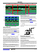
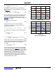
Operating Frequency
The ISL85410 operates at a default switching frequency of
500kHz if the FS pin is tied to V
CC
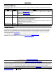
. Tie a resistor from the FS pin
to GND to program the switching frequency from 300kHz to
2MHz, as shown in Equation 4
.
Where:
t is the switching period in µs.
Synchronization Control
The frequency of operation can be synchronized up to 2MHz by
an external signal applied to the SYNC pin. The rising edge on the
SYNC triggers the rising edge of PHASE. To properly sync, the
external source must be at least 10% greater than the
programmed free running IC frequency.
Output Inductor Selection
The inductor value determines the converter’s ripple current.
Choosing an inductor current requires a somewhat arbitrary
choice of ripple current, I
. A reasonable starting point is 30% of
total load current. The inductor value can then be calculated
using Equation 5
:
Increasing the value of inductance reduces the ripple current and
thus, the ripple voltage. However, the larger inductance value
may reduce the converter’s response time to a load transient.
The inductor current rating should be such that it will not saturate
in overcurrent conditions. For typical ISL85410 applications,
inductor values generally lie in the 10µH to 47µH range. In
general, higher V
OUT
will mean higher inductance.
R
FS
k108.75k
t 0.2s 1s–=
(EQ. 4)
FIGURE 46. R
FS
SELECTION vs f
SW
300
200
100
0
500 750 1000 1250 1500 1750 2000
f
SW
(kHz)
R
FS
(kΩ)
400
250
(EQ. 5)
L
V
IN
V
OUT
–
f
SW
I
--------------------------------
V
OUT
V
IN
----------------
=