
Data Sheet


LEDs
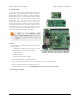
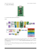
The A-Star 32U4 Micro has two indicator LEDs.
The yellow LED is connected to Arduino pin 13, or PC7. You can drive this pin high in a user program to turn this
LED on. The A-Star 32U4 Bootloader [http://www.pololu.com/docs/0J61/9] fades this LED on and off while it is waiting
for a sketch to be loaded.
The green LED is connected to PD5 and lights when the pin is driven low. While the board is running the A-Star
32U4 Bootloader or a program compiled in the Arduino environment, it will flash this LED when it is transmitting
data via the USB connection.
Connectors
The A-Star 32U4 includes a USB Micro-B connector that can be used to connect to a computer’s USB port via a USB
A to Micro-B cable [http://www.pololu.com/product/2072] (not included). The USB connection can be used to transmit
and receive data from the computer, and a preloaded USB bootloader makes it possible to program the board over
USB. The USB connection can also provide power to the A-Star.
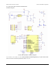
The board also has a 6-pin ISP header that allows it to be programmed with an external programmer, such as our
USB AVR programmer [http://www.pololu.com/product/1300]. Pin 1 of the header is indicated with a small white dot and
has an octagonal shape. Three of the pins on this header can be used as an SPI interface or as general-purpose digital
I/O, as shown in the pinout diagram. In the Arduino environment, you can refer to these three pins using either their
pin numbers or the names of their SPI functions (which are defined as aliases); for example, digitalRead(15) and
digitalRead(SCK) are equivalent.
Power
The A-Star 32U4 Micro can either be powered directly from the USB 5 V supply or from a separate source on the
VIN pin. The board features a power selection circuit that allows both USB and VIN to be connected at the same
time; if this is done, the A-Star will draw power from VIN.
USB power input: The A-Star can be powered from the USB 5 V bus voltage (VBUS) if it is connected to a USB
cable. It will draw power from USB only if VIN is disconnected. A resettable PTC fuse on VBUS makes it less likely
for the A-Star (and the connected computer or other device) to be damaged if too much current is drawn from the
USB connection.
VIN power input: The A-Star can be powered from VIN if you connect a 5.5 V to 15 V power supply (such as a
battery or wall power adapter) to the VIN and GND pins, with the positive terminal connected to VIN.
When powering the A-Star 32U4 Micro from VIN, a minimum voltage of 5.5 V is required to ensure that
the board’s 5 V supply is stable. Even if power is being provided to the A-Star via USB, connecting a
voltage higher than 0 V but lower than 5.5 V to VIN is not recommended, as this can interfere with the
power selection circuit and cause the 5 V line to drop (potentially triggering a brown-out reset).
5V power output: This pin provides access to the board’s 5 V supply, which comes from either the USB 5 V bus
voltage or a low-dropout (LDO) regulator on VIN, depending on which power source is connected. The regulator can
supply up to 100 mA, although some of this is used by the board itself (typically about 25 mA) or used to provide
current for the GPIO pins or 3.3 V power output (see below).
Pololu A-Star 32U4 User’s Guide © 2001–2014 Pololu Corporation
3. A-Star 32U4 Micro Page 7 of 47