
Data Sheet


3. A-Star 32U4 Micro
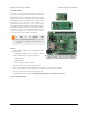
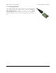
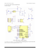
A-Star 32U4 Micro, top view.
3.1. A-Star 32U4 Micro pinout and components
Pinout
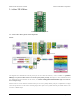
The diagram above identifies the I/O and power pins on the A-Star 32U4 Micro; it is also available as a printable
PDF [http://www.pololu.com/file/download/a-star-32u4-micro-pinout.pdf?file_id=0J796] (409k pdf). For more information about
the ATmega32U4 microcontroller on this board, see Atmel’s ATmega32U4 documentation [http://www.atmel.com/
devices/atmega32u4.aspx].
Printed on the A* circuit board are indicators that you can use to quickly identify each pin’s capabilities: a triangle
next to the pin means it can be used as an analog input, and a square wave symbol under the pin number means it can
be used as a PWM output.
Pololu A-Star 32U4 User’s Guide © 2001–2014 Pololu Corporation
3. A-Star 32U4 Micro Page 6 of 47