
Data Sheet

example, digitalRead(15) and digitalRead(SCK) are equivalent. If you have an SMT-only version of the A-Star,
it is possible to solder a shrouded box header [http://www.pololu.com/product/854] to this location; the outlines on the
board indicate the correct connector orientation.
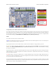
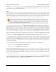
Power
The A-Star 32U4 Prime can either be powered directly from the USB 5 V supply or from an external voltage source,
which is regulated to 5 V by its onboard switching regulator. The slide switch on A* controls whether the external
source is connected to the input of the regulator, providing a convenient way to switch off external power to the A-
Star without unplugging any connections. The adjacent set of three pins provides a place to connect your own power
switch: to enable external power, connect the middle pin to ground (accessible through the upper pin).
When the A-Star is connected to a computer via USB, it will receive 5V power even when the power
switch is off. This can be useful if you want to upload or test a program without drawing external
power (to avoid draining a battery pack, for example).
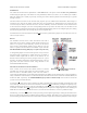
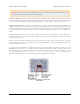
The board’s power selection circuit uses the TPS2113A power multiplexer [http://www.pololu.com/product/2596] from
Texas Instruments to choose whether its 5 V supply is sourced from USB or an external supply via the regulator,
allowing both sources to be connected at the same time and enabling the A-Star to safely and seamlessly transition
between them. The TPS2113A is configured to select external power unless the regulator output falls below about
4.5 V. If this happens, it will select the higher of the two sources, which will typically be the USB 5 V bus voltage if
the A* is connected to USB. The currently selected source is indicated by the STAT pin in the middle of the board;
this pin is an open-drain output that is low if the external power source is selected and high-impedance if the USB
supply is selected. The current limit of the TPS2113A is set to about 1.9 A. For more information about the power
multiplexer, see the TPS2113A datasheet [http://www.pololu.com/file/download/tps2113a.pdf?file_id=0J771] (1MB pdf).
In some situations, it might be undesirable for the A-Star 32U4 Prime to draw power from an external source when
it is connected to USB, even if the power switch is left on. If this is the case, the regulator can be disabled by driving
the regulator shutdown pin, SHDN, high; this shuts down the regulator and causes the power mux to fall back to
USB power. For example, this could allow a battery-powered system to automatically turn off the regulator while it
is connected to a computer.
The input voltage range of the regulator depends on the particular version of the A-Star 32U4 Prime:
• LV: 2.7 V to 11.8 V (see Section 5.3 for regulator details)
• SV: 5 V to 36 V (see Section 5.4 for regulator details)
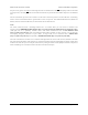
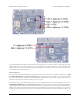
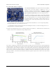
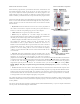
Reverse-protected and switched power inputs: The connection points labeled “Power In” are power inputs with
reverse-voltage protection that are controlled by the power switch. These are the recommended pins to use when
connecting an external power supply because they allow the A-Star’s reverse-voltage protection circuit to help
prevent it from being damaged by accidentally-reversed power connections, and they enable the A-Star’s power
switch to disconnect the supply.
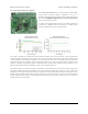
A number of different connectors can be soldered to the board and used to provide power, including a DC barrel jack
[http://www.pololu.com/product/1139] or a 3.5 mm screw terminal block [http://www.pololu.com/product/2444] (the assembled
versions of the board come with one or both of these populated).
Pololu A-Star 32U4 User’s Guide © 2001–2014 Pololu Corporation
5. A-Star 32U4 Prime Page 25 of 47