
Data Sheet

and prevent any presses on button A from being detected. You should remove the CS-GND jumper when no microSD
card is present, as asserting CS with no microSD card inserted can put the DO level shifter output into an undefined
state.
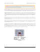
The CD (card detect) pin next to the connector can be used to detect the presence of a microSD card: it is floating
when a card is inserted and shorted to ground when a card is not present. Two additional SD data lines (DAT1 and
DAT2), which are unused in SPI mode, are also broken out for advanced uses.
LCD
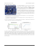
The A-Star 32U4 Prime has a mounting location for a 2×7 header where you can connect a character LCD
with the common HD44780 parallel interface [http://www.pololu.com/file/download/DMC50448N-AAE-AD.pdf?file_id=0J71]
(109k pdf). The A* is optionally available with a male header installed here and an 8×2 character LCD
[http://www.pololu.com/product/356] (with corresponding female header) included; on other versions, you can add your
own display using the connectors of your choice. A larger LCD can be connected with a ribbon cable
[http://www.pololu.com/product/973] and optionally a shrouded box header [http://www.pololu.com/product/898].
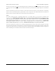
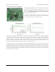
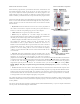
The LCD control lines are broken out to a column of through holes next to the LCD connector, labeled on the back
side of the board. By default, some of these are connected to I/O lines from the ATmega32U4 to allow control of the
LCD in 4-bit mode, but you can remap the connections by cutting the surface-mount jumpers indicated in the picture
below and making new connections between I/O lines and LCD control pins.
Pololu A-Star 32U4 User’s Guide © 2001–2014 Pololu Corporation
5. A-Star 32U4 Prime Page 23 of 47