
Data Sheet
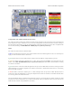
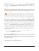
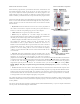

Buzzer and CS-GND jumpers on the A-
Star 32U4 Prime.
Pushbuttons
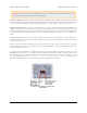
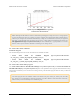
The A-Star 32U4 Prime has four pushbuttons: a reset button next to the power switch and three user pushbuttons
located along the right edge of the board. The user pushbuttons, labeled A, B, and C, are on Arduino pin 14 (PB3),
PD5, and Arduino pin 17 (PB0), respectively. Pressing one of these buttons pulls the associated I/O pin to ground
through a resistor.
The three buttons’ I/O lines are also used for other purposes: pin 14 is MISO on the SPI interface, PD5 and pin 17
control the green and red user LEDs, and all three pins are LCD data lines. Although these uses require the pins
to be driven by the AVR (or SPI slave devices in the case of MISO), resistors in the button circuits ensure that the
A-Star will not be damaged even if the corresponding buttons are pressed at the same time, nor will SPI or LCD
communications be disrupted. The functions in the AStar32U4Prime library take care of configuring the pins, reading
and debouncing the buttons, and restoring the pins to their original states.
Note that button A cannot be used if the microSD CS pin is tied to ground with a jumper (see microSD card connector
and level shifters below).
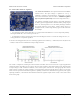
Buzzer
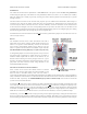
The assembled versions of the A-Star 32U4 Prime come with a
buzzer that can be used to generate simple sounds and music. The
buzzer is not present on the SMT-only versions, but the buzzer
driver circuit is still populated, allowing you to solder in your own
buzzer or speaker. The stock buzzer is available as part of the A-
Star 32U4 Prime accessory pack [http://www.pololu.com/product/3110].
A through-hole jumper next to the buzzer provides a way to connect
the buzzer input to digital pin 6 (which also serves as OC4D, a
hardware PWM output from the AVR’s 10-bit Timer4). If you
alternate between driving the buzzer pin high and low at a given
frequency, the buzzer will produce sound at that frequency. You can
play notes and music with the buzzer using functions in the
AStar32U4PrimeBuzzer library.
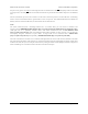
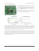
microSD card connector and level shifters
Some versions of the A-Star 32U4 Prime include an onboard
microSD card connector that enables the microcontroller to read
from and write to microSD memory cards. The card socket is
connected to the SPI interface on the ATmega32U4 through level-shifting circuits, allowing the 5 V microcontroller to
safely communicate with standard 3.3 V SD cards. DI, DO, and SCLK on the card are connected to MOSI, MISO, and
SCK on the AVR, respectively. The Arduino SD library [http://arduino.cc/en/Reference/SD] can be used to access the file
system on an inserted microSD card.
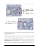
A fourth pin, CS (chip select), must be held low to enable communication with the microSD card in SPI mode. This
can be done by connecting one of the microcontroller’s I/O lines to CS (the SD library examples use digital pin 4 by
default) and driving the pin low to select the microSD card. The CS line also controls whether the output of the DO
level shifter is enabled: when CS is high, the level shifter places its output into a high-impedance state, allowing the
MISO line to be driven by other SPI slave devices, used as an LCD control line, or read as a pushbutton input.
Alternatively, you can tie CS low more easily by shorting it to the adjacent ground pin, causing the microSD card to
always be selected and the DO level shifter output to always be enabled. This allows you to avoid using an extra I/O
line and making an additional connection, but the DO level shifter output will override the pushbutton on the same pin
Pololu A-Star 32U4 User’s Guide © 2001–2014 Pololu Corporation
5. A-Star 32U4 Prime Page 22 of 47