
Data Sheet

5.2. A-Star 32U4 Prime pinout and components
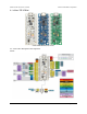
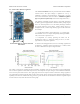
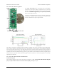
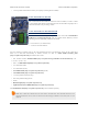
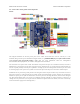
Pinout
This diagram identifies the I/O and power pins on the A-Star 32U4 Prime (LV and SV versions); it is also
available (along with the power distribution diagram below) as a printable PDF [http://www.pololu.com/file/download/
a_star_32u4_prime_pinout_power.pdf?file_id=0J847] (1MB pdf). For more information about the ATmega32U4
microcontroller and its peripherals, see Atmel’s ATmega32U4 documentation.
The outermost rows of pins of the A-Star 32U4 Prime correspond to the pins on an Arduino Leonardo, and each is
duplicated on a second inner row for more convenient access. Printed on the A* circuit board are indicators that you
can use to quickly identify each I/O pin’s capabilities: a triangle by the inner through hole means the pin can be used
as an analog input, and a square wave symbol next to the hole pair means the pin can be used as a PWM output.
Additional rows of power and ground pins also run along most of the I/O pins to allow easy connections to devices
like sensors and servos. The innermost pin is ground, and the second-innermost is power, which is not connected by
default. The power pins are split into three buses: one bus for pins A0–A4 along the bottom, and two buses along the
top, split between digital pins 7 and 8. You can configure each bus separately by using a jumper to connect it to a
voltage source of your choice. (Access points for 5V and VIN are adjacent to the A0–A4 bus, so it can be conveniently
connected to either supply with a shorting block.)
Pololu A-Star 32U4 User’s Guide © 2001–2014 Pololu Corporation
5. A-Star 32U4 Prime Page 20 of 47