
Data Sheet
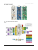
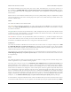
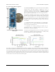
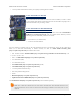
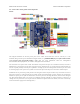

This diagram identifies the I/O and power pins on the A-Star 32U4 Mini (ULV, LV, and SV versions); it is
also available as a printable PDF [http://www.pololu.com/file/download/a-star-32u4-mini-pinout.pdf?file_id=0J784] (269k pdf).
For more information about the ATmega32U4 microcontroller and its peripherals, see Atmel’s ATmega32U4
documentation.
Printed on the A* circuit board are indicators that you can use to quickly identify each pin’s capabilities: a triangle
next to the pin means it can be used as an analog input, and a square wave symbol under the pin number means it can
be used as a PWM output.
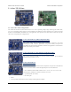
LEDs
The A-Star 32U4 Mini has three indicator LEDs.
The yellow LED is connected to Arduino pin 13, or PC7. You can drive this pin high in a user program to turn this
LED on. The A-Star 32U4 Bootloader [http://www.pololu.com/docs/0J61/9] fades this LED on and off while it is waiting
for a sketch to be loaded.
The green LED is connected to the pin labeled TXL, or PD5, and lights when the pin is driven low. While the board
is running the A-Star 32U4 Bootloader or a program compiled in the Arduino environment, it will flash this LED
when it is transmitting data via the USB connection.
The red LED is connected to the pin labeled RXL (usable as Arduino pin 17), or PB0, and lights when the pin
is driven low. While the board is running the A-Star 32U4 Bootloader or a program compiled in the Arduino
environment, it will flash this LED when it is receiving data via the USB connection.
Connectors
The A-Star 32U4 includes a USB Micro-B connector that can be used to connect to a computer’s USB port via a USB
A to Micro-B cable [http://www.pololu.com/product/2072] (not included). The USB connection can be used to transmit
and receive data from the computer, and a preloaded USB bootloader makes it possible to program the board over
USB. The USB connection can also provide power to the A-Star.
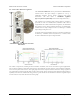
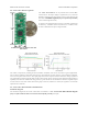
The board also has a 6-pin ISP header that allows it to be programmed with an external programmer, such as our
USB AVR programmer [http://www.pololu.com/product/1300]. Pin 1 of the header is indicated with a small dot and has
an octagonal shape.
Power
The A-Star 32U4 Mini can either be powered directly from the USB 5 V supply or from an external voltage source,
which is regulated to 5 V by its onboard switching regulator.
The board’s power selection circuit uses the TPS2113A power multiplexer [http://www.pololu.com/product/2596] from
Texas Instruments to choose whether its 5 V supply is sourced from USB or an external supply via the regulator,
allowing both sources to be connected at the same time and enabling the A-Star to safely and seamlessly transition
between them. The TPS2113A is configured to select external power unless the regulator output falls below about
4.5 V. If this happens, it will select the higher of the two sources, which will typically be the USB 5 V bus voltage if
the A* is connected to USB. The currently selected source is indicated by the STAT pin in the middle of the board;
this pin is an open-drain output that is low if the external power source is selected and high-impedance if the USB
supply is selected. The current limit of the TPS2113A is set to about 1.9 A. For more information about the power
multiplexer, see the TPS2113A datasheet [http://www.pololu.com/file/download/tps2113a.pdf?file_id=0J771] (1MB pdf).
In some situations, it might be undesirable for the A-Star 32U4 Mini to draw power from an external source when it
is connected to USB. If this is the case, the regulator can be disabled by driving the regulator shutdown pin, SHDN,
Pololu A-Star 32U4 User’s Guide © 2001–2014 Pololu Corporation
4. A-Star 32U4 Mini Page 12 of 47