Pololu A-Star 32U4 User’s Guide © 2001–2014 Pololu Corporation Pololu A-Star 32U4 User’s Guide http://www.pololu.
Pololu A-Star 32U4 User’s Guide 1. Overview . . . . . . . . . . . . . . . . . . . . . . . 1.1. Supported operating systems . . . . . . . . . 2. Contacting Pololu . . . . . . . . . . . . . . . . . . . 3. A-Star 32U4 Micro . . . . . . . . . . . . . . . . . . 3.1. A-Star 32U4 Micro pinout and components . 3.2. A-Star 32U4 Micro schematic and dimensions 4. A-Star 32U4 Mini . . . . . . . . . . . . . . . . . . 4.1. A-Star 32U4 Mini pinout and components . . 4.2. A-Star 32U4 Mini ULV regulator . . . . . . . 4.3.
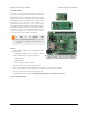
Pololu A-Star 32U4 User’s Guide © 2001–2014 Pololu Corporation 1. Overview The Pololu A-Star 32U4 microcontroller boards are general-purpose programmable modules based on Atmel’s ATmega32U4 AVR microcontroller, which has 32 KB of flash program memory, 2.5 KB of RAM, and built-in USB functionality. Each A-Star (abbreviated A*) adds onboard components and connectors that support the microcontroller and make it easier to use.
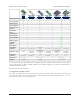
Pololu A-Star 32U4 User’s Guide A-Star 32U4 Micro © 2001–2014 Pololu Corporation A-Star 32U4 Mini ULV Microcontroller: ATmega32U4 A-Star 32U4 Mini LV A-Star 32U4 Mini SV A-Star 32U4 Prime LV A-Star 32U4 Prime SV ATmega32U4 ATmega32U4 User I/O lines: 18 26 26 PWM outputs: 7 7 7 Analog inputs: 8 12 12 Ground access points: 2 4 43 User LEDs: 2 3 3 User pushbuttons: — — 3 Reset button: Power switch: Buzzer option: microSD option: LCD option: Operating voltage: Regulator type:
Pololu A-Star 32U4 User’s Guide © 2001–2014 Pololu Corporation 2. Contacting Pololu We would be delighted to hear from you about any of your projects and about your experience with the Pololu A-Stars. You can contact us [http://www.pololu.com/contact] directly or post on our forum [http://forum.pololu.com/]. Tell us what we did well, what we could improve, what you would like to see in the future, or anything else you would like to say! 2.
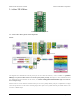
Pololu A-Star 32U4 User’s Guide © 2001–2014 Pololu Corporation 3. A-Star 32U4 Micro A-Star 32U4 Micro, top view. 3.1. A-Star 32U4 Micro pinout and components Pinout The diagram above identifies the I/O and power pins on the A-Star 32U4 Micro; it is also available as a printable PDF [http://www.pololu.com/file/download/a-star-32u4-micro-pinout.pdf?file_id=0J796] (409k pdf). For more information about the ATmega32U4 microcontroller on this board, see Atmel’s ATmega32U4 documentation [http://www.atmel.
Pololu A-Star 32U4 User’s Guide © 2001–2014 Pololu Corporation LEDs The A-Star 32U4 Micro has two indicator LEDs. The yellow LED is connected to Arduino pin 13, or PC7. You can drive this pin high in a user program to turn this LED on. The A-Star 32U4 Bootloader [http://www.pololu.com/docs/0J61/9] fades this LED on and off while it is waiting for a sketch to be loaded. The green LED is connected to PD5 and lights when the pin is driven low.
Pololu A-Star 32U4 User’s Guide © 2001–2014 Pololu Corporation 3V3 power output: This pin gives access to the output of the internal 3.3 V regulator inside the ATmega32U4. The microcontroller uses this regulated voltage for USB signaling, but up to about 50 mA is available for powering external circuits or devices.
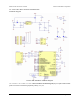
Pololu A-Star 32U4 User’s Guide © 2001–2014 Pololu Corporation 3.2. A-Star 32U4 Micro schematic and dimensions Schematic diagram Pololu A-Star 32U4 Micro schematic diagram. This schematic is also available as a PDF: A-Star 32U4 Micro schematic diagram [http://www.pololu.com/file/download/ pololu-a-star-32u4-micro-schematic-diagram.pdf?file_id=0J742] (253k pdf). 3.
Pololu A-Star 32U4 User’s Guide © 2001–2014 Pololu Corporation Dimension diagram A dimension diagram of the A-Star 32U4 Micro is available as a PDF: A-Star 32U4 Micro dimension diagram [http://www.pololu.com/file/download/pololu-a-star-32u4-micro-dimension-diagram.pdf?file_id=0J747] (255k pdf). 3.
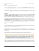
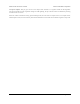
Pololu A-Star 32U4 User’s Guide © 2001–2014 Pololu Corporation 4. A-Star 32U4 Mini A-Star 32U4 Mini ULV, LV, and SV. 4.1. A-Star 32U4 Mini pinout and components Pinout 4.
Pololu A-Star 32U4 User’s Guide © 2001–2014 Pololu Corporation This diagram identifies the I/O and power pins on the A-Star 32U4 Mini (ULV, LV, and SV versions); it is also available as a printable PDF [http://www.pololu.com/file/download/a-star-32u4-mini-pinout.pdf?file_id=0J784] (269k pdf). For more information about the ATmega32U4 microcontroller and its peripherals, see Atmel’s ATmega32U4 documentation.
Pololu A-Star 32U4 User’s Guide © 2001–2014 Pololu Corporation high; this shuts down the regulator and causes the power mux to fall back to USB power. For example, this could allow a battery-powered device to turn off the regulator and avoid draining its battery while it is connected to a computer. The input voltage range of the regulator depends on the particular version of the A-Star 32U4 Mini: • ULV: 0.5 V to 5.5 V (see Section 4.2 for regulator details) • LV: 2.7 V to 11.8 V (see Section 4.
Pololu A-Star 32U4 User’s Guide © 2001–2014 Pololu Corporation 4.2. A-Star 32U4 Mini ULV regulator The A-Star 32U4 Mini ULV can be powered from a 0.5 V to 5.5 V external source. The input voltage is regulated to 5 V by a TPS61202 switching step-up (boost) converter from Texas Instruments. (We also make a standalone regulator [http://www.pololu.com/product/2562] based on this integrated circuit.
Pololu A-Star 32U4 User’s Guide © 2001–2014 Pololu Corporation 4.3. A-Star 32U4 Mini LV regulator The A-Star 32U4 Mini LV can be powered from a 2.7 V to 11.8 V external source. The input voltage is regulated to 5 V by a TPS63061 switching step-up/step-down (buck-boost) converter from Texas Instruments. (We also make a standalone regulator [http://www.pololu.com/product/2123] based on this integrated circuit.
Pololu A-Star 32U4 User’s Guide © 2001–2014 Pololu Corporation 4.4. A-Star 32U4 Mini SV regulator The A-Star 32U4 Mini SV can be powered from a 5 V to 36 V external source. The input voltage is regulated to 5 V by a 500 mA ISL85415 switching step-down (buck) converter from Intersil. (We also make a standalone regulator [http://www.pololu.com/product/2843] based on this integrated circuit.
Pololu A-Star 32U4 User’s Guide © 2001–2014 Pololu Corporation Dimension diagrams Dimension diagrams for the A-Star 32U4 Minis are available as PDFs: • A-Star 32U4 Mini ULV (274k pdf) dimension diagram [http://www.pololu.com/file/download/ac02a- dimensions.pdf?file_id=0J781] • A-Star 32U4 Mini LV dimension diagram [http://www.pololu.com/file/download/ac02b-dimensions.pdf?file_id=0J782] (292k pdf) • A-Star 32U4 Mini SV dimension diagram [http://www.pololu.com/file/download/ac02c-dimensions.
Pololu A-Star 32U4 User’s Guide © 2001–2014 Pololu Corporation 5. A-Star 32U4 Prime A-Star 32U4 Prime LV microSD. A-Star 32U4 Prime SV microSD. 5.1. A-Star 32U4 Prime configurations The A-Star 32U4 Prime LV (blue solder mask, 2.7 V to 11.8 V operating voltage range) and SV (green solder mask, 5 V to 36 V operating voltage range) are each available in five different versions, allowing you to choose the right amount of customizability and features for your application.
Pololu A-Star 32U4 User’s Guide © 2001–2014 Pololu Corporation • 1×2 low-profile male header for battery level jumper (shorting block included) A-Star 32U4 Prime LV microSD A-Star 32U4 Prime SV microSD This version adds the microSD card connector and level shifters, as well as a third 1×2 low-profile male header and shorting block for the microSD CS jumper, but is otherwise identical to the preceding version.
Pololu A-Star 32U4 User’s Guide © 2001–2014 Pololu Corporation 5.2. A-Star 32U4 Prime pinout and components Pinout This diagram identifies the I/O and power pins on the A-Star 32U4 Prime (LV and SV versions); it is also available (along with the power distribution diagram below) as a printable PDF [http://www.pololu.com/file/download/ a_star_32u4_prime_pinout_power.pdf?file_id=0J847] (1MB pdf).
Pololu A-Star 32U4 User’s Guide © 2001–2014 Pololu Corporation Compatibility with Arduino shields and accessories The A-Star 32U4 Prime matches the Arduino Leonardo and the Arduino Uno R3 in the shape of its circuit board and the arrangement of its pins.
Pololu A-Star 32U4 User’s Guide © 2001–2014 Pololu Corporation Pushbuttons The A-Star 32U4 Prime has four pushbuttons: a reset button next to the power switch and three user pushbuttons located along the right edge of the board. The user pushbuttons, labeled A, B, and C, are on Arduino pin 14 (PB3), PD5, and Arduino pin 17 (PB0), respectively. Pressing one of these buttons pulls the associated I/O pin to ground through a resistor.
Pololu A-Star 32U4 User’s Guide © 2001–2014 Pololu Corporation and prevent any presses on button A from being detected. You should remove the CS-GND jumper when no microSD card is present, as asserting CS with no microSD card inserted can put the DO level shifter output into an undefined state. The CD (card detect) pin next to the connector can be used to detect the presence of a microSD card: it is floating when a card is inserted and shorted to ground when a card is not present.
Pololu A-Star 32U4 User’s Guide © 2001–2014 Pololu Corporation The AStar32U4PrimeLCD library provides functions to display data on a connected LCD. It is designed to gracefully handle alternate use of the LCD data lines by only changing pin states when needed for an LCD command, after which it will restore them to their previous states. This allows the LCD data lines to be used for other functions (such as pushbutton inputs and LED drivers).
Pololu A-Star 32U4 User’s Guide © 2001–2014 Pololu Corporation example, digitalRead(15) and digitalRead(SCK) are equivalent. If you have an SMT-only version of the A-Star, it is possible to solder a shrouded box header [http://www.pololu.com/product/854] to this location; the outlines on the board indicate the correct connector orientation.
Pololu A-Star 32U4 User’s Guide © 2001–2014 Pololu Corporation Warning: You must never connect different power sources to multiple Power In locations at the same time, as doing so will create a short between the supplies. VIN power output (or alternative input): When power is supplied through the Power In pins, the VIN pin can be used as an output to supply reverse-protected and switched power to other devices.
Pololu A-Star 32U4 User’s Guide © 2001–2014 Pololu Corporation 5.3. A-Star 32U4 Prime LV regulator The A-Star 32U4 Prime LV can be powered from a 2.7 V to 11.8 V external source. The input voltage is regulated to 5 V by a TPS63061 switching step-up/step-down (buck-boost) converter from Texas Instruments. (We also make a standalone regulator [http://www.pololu.com/product/2123] based on this integrated circuit.
Pololu A-Star 32U4 User’s Guide © 2001–2014 Pololu Corporation 5.4. A-Star 32U4 Prime SV regulator The A-Star 32U4 Prime SV can be powered from a 5 V to 36 V external source. The input voltage is regulated to 5 V by a 1 A ISL85410 switching step-down (buck) converter from Intersil. (We also make a standalone regulator [http://www.pololu.com/product/2831] based on this integrated circuit.
Pololu A-Star 32U4 User’s Guide © 2001–2014 Pololu Corporation Typical dropout voltage of the 5 V regulator on the A-Star 32U4 Prime SV. Note: Although the ISL85410 is rated for a maximum operating input voltage of 36 V, it is not appropriate to power the Prime SV with a 36 V battery, as battery voltages can be much higher than nominal voltages when they are charged.
Pololu A-Star 32U4 User’s Guide © 2001–2014 Pololu Corporation When the demo program starts, you should see the words “A-Star Prime” and then “Demo Program” appear. If you do not see any text on the LCD, you may need to adjust the contrast potentiometer. The demo program is not usable without an LCD. If a buzzer is soldered in and the buzzer shorting block is installed, you should also hear a beep when the demo program starts. After the program has started, press the B button to proceed to the main menu.
Pololu A-Star 32U4 User’s Guide © 2001–2014 Pololu Corporation 6. Getting started 6.1. Installing Windows drivers If you use Windows XP, you will need to have either Service Pack 3 [http://www.microsoft.com/downloads/ details.aspx?FamilyId=68C48DAD-BC34-40BE-8D85-6BB4F56F5110] or Hotfix KB918365 installed before installing the A-Star drivers. Some users who installed the hotfix have reported problems which were solved by upgrading to Service Pack 3, so we recommend Service Pack 3 over the hotfix.
Pololu A-Star 32U4 User’s Guide © 2001–2014 Pololu Corporation you connect an A-Star to your computer, Windows will take several seconds to recognize the device and configure itself properly. The first time you program the A-Star, Windows will again take several seconds to recognize the AStar’s USB bootloader, and this could cause the programming operation to fail the first time.
Pololu A-Star 32U4 User’s Guide © 2001–2014 Pololu Corporation 4. In the Tools > Board menu, select the “Pololu A-Star 32U4” entry. If you do not see the A-Star listed in the Board menu, then the add-on is probably not installed correctly. Try doing step 2 again and restarting the Arduino IDE. Selecting the Pololu A-Star 32U4 in the Boards menu. 5. In the Tools > Port menu, select the port for the A-Star.
Pololu A-Star 32U4 User’s Guide © 2001–2014 Pololu Corporation Selecting the Blink example in the Arduino IDE. 7. Press the “Upload” button to compile the sketch and upload it to the A-Star. If everything goes correctly, you will see the message “Done uploading” appear near the bottom of the window. If you are using Windows and you have not previously programmed an A-Star on this USB port, then Windows might take several seconds to recognize the A-Star bootloader.
Pololu A-Star 32U4 User’s Guide © 2001–2014 Pololu Corporation Uploading a sketch to the A-Star using the Arduino IDE. 8. If you uploaded the Blink sketch, then the A-Star’s yellow LED should be blinking once every two seconds. However, we ship the A-Stars with that same example already programmed onto it, so you might not be convinced that anything has changed. Try changing the delay values in the sketch to something else and uploading again to see if you can change the speed of the LED.
Pololu A-Star 32U4 User’s Guide © 2001–2014 Pololu Corporation 6.3. Programming using avr-gcc and AVRDUDE This section explains how to program the A-Star boards using the avr-gcc toolchain and AVRDUDE. This section is intended for advanced users who do not want to use the Arduino IDE as described in Section 6.2. Getting the prerequisites If you are using Windows, we recommend downloading WinAVR [http://winavr.sourceforge.
Pololu A-Star 32U4 User’s Guide © 2001–2014 Pololu Corporation all: $(TARGET).hex clean: rm -f *.o *.hex *.obj *.hex %.hex: %.obj avr-objcopy -R .eeprom -O ihex $< $@ %.obj: $(OBJECT_FILES) $(CC) $(CFLAGS) $(OBJECT_FILES) $(LDFLAGS) -o $@ program: $(TARGET).hex avrdude -p $(MCU) -c avr109 -P $(PORT) -U flash:w:$(TARGET).hex Make sure that the PORT variable in the Makefile is set to the name of the A-Star’s virtual serial port. In Windows, \\\\.
Pololu A-Star 32U4 User’s Guide © 2001–2014 Pololu Corporation 7. A-Star Arduino libraries The A-Star can be programmed directly from the Arduino IDE as described in Section 6.2. To help interface with the on-board hardware on the A-Star 32U4 Prime LV, we provide the AStar32U4Prime library. The library makes it easy to display information on the LCD, play sounds and music from the buzzer, use the three pushbuttons, control all three user LEDs, and read the battery voltage level.
Pololu A-Star 32U4 User’s Guide © 2001–2014 Pololu Corporation 8. The A-Star 32U4 USB interface The A-Star 32U4 boards are based on a single AVR ATmega32U4 microcontroller that runs the user program and also handles the USB connection to the computer. The AVR has a full-speed USB transceiver built into it and can be programmed to present almost any type of USB device interface to the computer. USB is an asymmetric system that consists of a single “host” connected to multiple “devices”.
Pololu A-Star 32U4 User’s Guide © 2001–2014 Pololu Corporation The Windows 8 Device Manager in “Devices by connection” mode, showing that the A-Star is a composite device. On a Linux computer, you can see details about the A-Star’s USB interface by running lsusb Terminal. The virtual serial port can be found by running ls /dev/ttyACM* in a Terminal. On a Mac OS X computer, the virtual serial port can be found by running ls -v -d 1ffb: /dev/tty.usbmodem* in a in a Terminal.
Pololu A-Star 32U4 User’s Guide © 2001–2014 Pololu Corporation 9. The A-Star 32U4 Bootloader The A-Star 32U4 boards come with a USB bootloader that can be used in conjunction with the Arduino IDE or AVRDUDE to load new programs onto an A-Star. This section documents some technical details of the bootloader for advanced users who want to better understand how it works. If you just want to get started using your A-Star, it is fine to skip this section.
Pololu A-Star 32U4 User’s Guide © 2001–2014 Pololu Corporation The startup logic for the A-Star 32U4 bootloader. Brown-out detection Unlike many other ATmega32U4 boards, the A-Stars have brown-out detection enabled. The brown-out threshold is 4.3 V, and if the voltage on VCC goes below this then the AVR will reset. The bootloader was designed so that the user program can detect brown-out resets. To do so, check to see if the BORF bit in the MCUSR register is set, and then clear it later.
Pololu A-Star 32U4 User’s Guide © 2001–2014 Pololu Corporation pinMode(13, OUTPUT); if (MCUSR & (1 << BORF)) { // A brownout reset occurred. Blink the LED // quickly for 2 seconds. for(uint8_t i = 0; i < 10; i++) { digitalWrite(13, HIGH); delay(100); digitalWrite(13, LOW); delay(100); } } MCUSR = 0; 9.
Pololu A-Star 32U4 User’s Guide © 2001–2014 Pololu Corporation 10. Reviving an unresponsive A-Star In order to load a new program onto your A-Star, you will need to get it into bootloader mode and send programming commands to it over its virtual serial port using appropriate software.
Pololu A-Star 32U4 User’s Guide © 2001–2014 Pololu Corporation 5. After 8 seconds, the bootloader will exit and attempt to run the sketch again. Wait for the bootloader to exit. Verify that either the “Port” menu is grayed out or no ports in it are selected. 6. Click the Upload button. The Arduino IDE will compile your sketch and start uploading it. 7. As soon as the large status bar near the bottom of the IDE says “Uploading…”, press reset the board twice to get into bootloader mode.
Pololu A-Star 32U4 User’s Guide © 2001–2014 Pololu Corporation 10.2. Reviving using AVRDUDE This section explains a special method for reviving an A-Star using the command-line utility AVRDUDE [http://www.nongnu.org/avrdude/] in case your usual method of programming is not working. AVRDUDE stands for “AVR Downloader/UploaDEr”, and it is compatible with the A-Star bootloader. If you have an A-Star 32U4 Micro, you should connect a momentary pushbutton [http://www.pololu.
Pololu A-Star 32U4 User’s Guide © 2001–2014 Pololu Corporation 11. Related Resources To learn more about using the Pololu A-Star boards, see the following list of resources: • The Arduino IDE has many examples [http://arduino.cc/en/Tutorial/HomePage] that can run on the A-Stars. • The Arduino website has a Language Reference [http://arduino.cc/en/Reference/HomePage], a wiki called the The Arduino Playground [http://playground.arduino.cc/], and other resources.