
Data Sheet


DMOS Microstepping Driver with Translator
and Overcurrent Protection
A4988
14
Allegro MicroSystems, Inc.
115 Northeast Cutoff
Worcester, Massachusetts 01615-0036 U.S.A.
1.508.853.5000; www.allegromicro.com
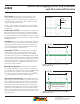
Figure 9. Decay Modes for Half-Step IncrementsFigure 8. Decay Mode for Full-Step Increments
Phase 2
I
OUT2A
Direction = H
(%)
Phase 1
I
OUT1A
Direction = H
(%)
STEP
Home Microstep Position
Home Microstep Position
100.00
70.71
–70.71
0.00
–100.00
100.00
70.71
–70.71
0.00
–100.00
Slow
Slow
*With ROSC pin tied to GND
Home Microstep Position
Home Microstep Position
100.00
70.71
–70.71
0.00
–100.00
100.00
70.71
–70.71
0.00
–100.00
Phase 2
I
OUT2B
Direction = H
(%)
Phase 1
I
OUT1A
Direction = H
(%)
STEP
Slow
Mixed
Mixed*
Mixed*
Slow
Mixed
Slow
Mixed
Mixed
Slow
Mixed
Slow
Mixed
Slow
Slow
0.00
100.00
92.39
70.71
38.27
–38.27
–70.71
–92.39
–100.00
0.00
100.00
92.39
70.71
38.27
–38.27
–70.71
–92.39
–100.00
Phase 2
I
OUT2B
Direction = H
(%)
Phase 1
I
OUT1A
Direction = H
(%)
Home Microstep Position
Slow
Mixed
Slow
Slow
Mixed
Slow
Mixed
Slow
MixedMixed
STEP
Slow
Mixed*
Mixed*
*
With ROSC pin tied to GND
Figure 10. Decay Modes for Quarter-Step Increments
DIR= H
DIR= H
DIR= H