
Data Sheet


Power for the switch’s logic needs to be applied to GND and VCC and must be between 2.5 V and
5.5 V. Many microcontroller boards have a 3.3 V or 5 V line that powers the microcontroller and would
also be suitable for powering the RC switch.
The OUT line can be connected to a digital input pin on the microcontroller.
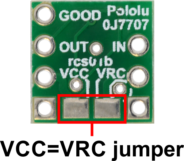
Power jumper
The setup described above involves two separate power supplies. For some applications, this setup
can be simplified by bridging the VCC=VRC power jumper on the bottom of the board. This allows you
to either power the microcontroller and RC switch from the RC receiver’s power supply or to power the
RC receiver and RC switch from the microcontroller’s power supply.
2.3. Schematic Diagram for the RC Switch with Digital Output
The schematic diagram of the Pololu RC Switch with Digital Output is shown below:
Pololu RC Switch User’s Guide © 2001–2017 Pololu Corporation
2. RC Switch with Digital Output Page 9 of 45