
Data Sheet


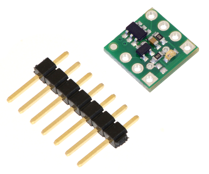
Pololu RC Switch with Digital Output. The header pins can be soldered in and used to connect the RC
switch to perfboards or breadboards [https://www.pololu.com/category/28/solderless-breadboards].
Pololu RC Switch with Digital Output with
included hardware.
2.2. Connecting the RC Switch with Digital Output
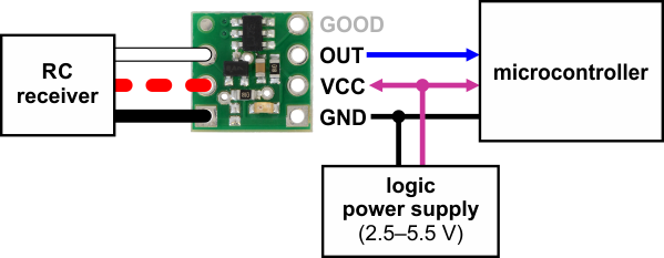
The typical way to connect the Pololu RC Switch with Digital Output is shown in the diagram below:
Typical wiring diagram for the Pololu RC Switch with Digital Output.
The RC switch can be plugged directly into an RC receiver or servo controller using a Female-
Female servo extension cable. These can be found in our Servo Cables [https://www.pololu.com/category/
112/servo-cables] category. The switch will read the signal from the RC receiver, but in the default
configuration it will not draw or supply any power to the receiver, so the power wire is optional. The
receiver will need its own power source.
Pololu RC Switch User’s Guide © 2001–2017 Pololu Corporation
2. RC Switch with Digital Output Page 8 of 45