
Data Sheet


2. RC Switch with Digital Output
2.1. Components of the RC Switch with Digital Output
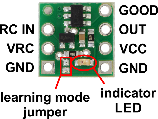
Pololu RC Switch with Digital Output, labeled top view.
The Pololu RC Switch with Digital Output has 7 through holes spaced 0.1″ apart that fit 0.1″ header
pins.
RC interface
The GND, VRC, and RC IN pins make up the switch’s RC interface and can be connected directly to
an RC receiver or servo controller:
• The GND pin is the ground or reference voltage.
• The VRC pin connects to the RC power line. The power from VRC is not used by default,
but a jumper on the bottom of the board can be bridged with solder to power the board from
VRC.
• The RC IN pin is the RC signal input. The switch measures the width of pulses on this line
and uses that to decide whether to activate or not.
Power
Pololu RC Switch User’s Guide © 2001–2017 Pololu Corporation
2. RC Switch with Digital Output Page 6 of 45