
Data Sheet


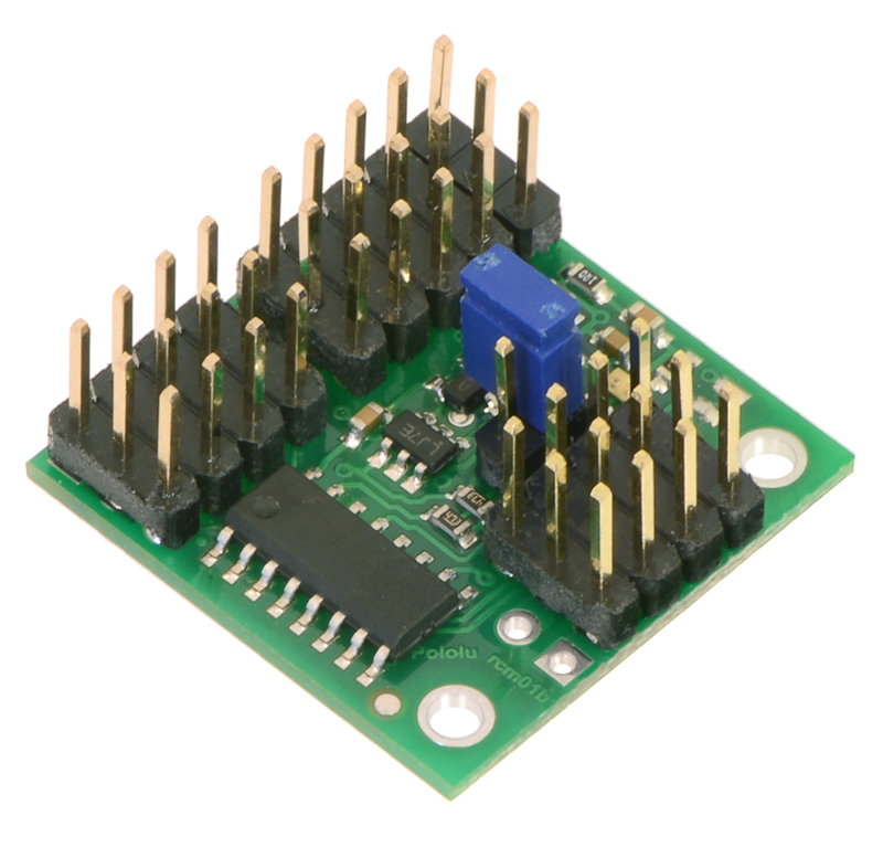
Pololu 4-Channel RC Multiplexer
(Assembled).
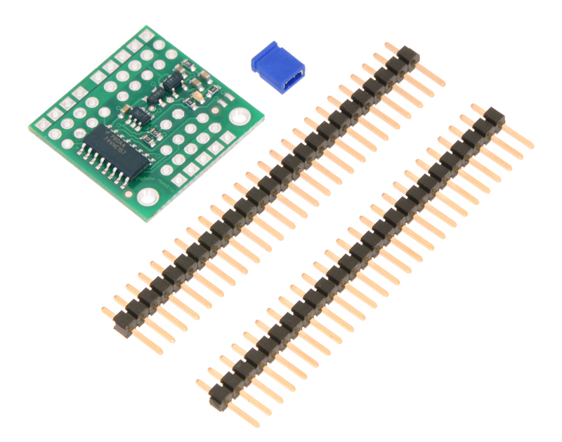
Pololu 4-Channel RC Servo Multiplexer
(Partial Kit) with included hardware.
6.2. Connecting the 4-Channel RC Servo Multiplexer
The RC multiplexer pins are spaced 0.1″ apart so the servo inputs can be plugged directly into an
RC receiver or servo controller using a Female-Female servo extension cable. These can be found
in our Servo Cables [https://www.pololu.com/category/112/servo-cables] category. The column of pins along
the outside edge of the board is GND (ground) and the column in the middle is power.
We recommend that you connect the SEL and M1–M4 inputs to a single “master” RC device, such
as an RC receiver or servo controller. The master device should have a power source that supplies
power the RC multiplexer. The power supplied by the master should be between 2.5 and 16 V and it
must be capable of supplying the current that the servos connected to the outputs draw.
We recommend that you connect the S1–S4 inputs to a single “slave” RC device, such as an RC
receiver or servo controller. The slave device will need a source of power. You can either connect the
slave power directly to the slave device or you can connect it to the GND/VS pin pair next to S1.
The OUT1–OUT4 outputs can be directly connected to standard RC servos.
The master RC device can use the SEL line to select which device controls the outputs. When the
switch is active, the signal received on S1 will be reflected on OUT1, so a device sending pulses to S1
can control a servo or ESC connected to OUT1. When the switch is not active, OUT1 will reflect the
input on M1. The same applies to channels 2–4.
6.3. Schematic Diagram for the 4-Channel RC Servo Multiplexer
The schematic diagram of the 4-Channel RC Servo Multiplexer is shown below:
Pololu RC Switch User’s Guide © 2001–2017 Pololu Corporation
6. Pololu 4-Channel RC Servo Multiplexer Page 35 of 45