
Data Sheet


6. Pololu 4-Channel RC Servo Multiplexer
6.1. Components of the 4-Channel RC Servo Multiplexer
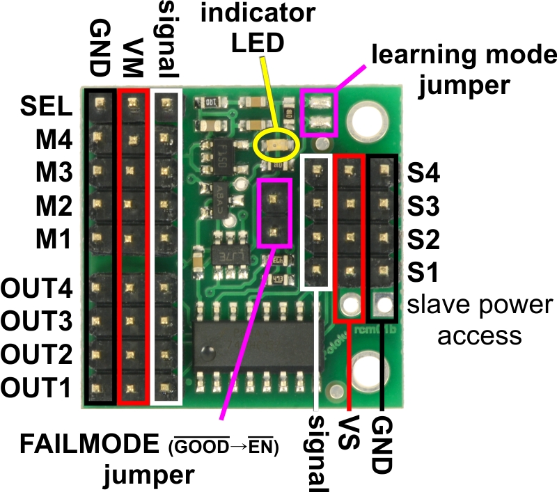
Pololu 4-Channel RC Servo Multiplexer (Assembled),
labeled pinout.
RC interface
The Pololu 4-Channel RC Servo Multiplexer has a total of 13 RC servo channels:
• The four inputs M1–M4 are called the master inputs.
• The four inputs S1–S4 are called the slave inputs.
• The four outputs OUT1–OUT4 are the main outputs of the device.
• The signal on the SEL input channel determines whether the outputs map to the master
inputs or the slave inputs.
This guide uses the terms active, activated, and activation to refer to the active state of the switch. For
the RC multiplexer, active means that the outputs reflect the slave inputs. By default, the switch will
not be active and the master inputs will show up on the outputs.
Each servo channel consists of three pins: GND, power, and signal. As shown in the diagram above,
the GND (ground) pins are on the edge of the board and the power pins are in the middle between
GND and signal. All ground pins are internally connected on the board.
Pololu RC Switch User’s Guide © 2001–2017 Pololu Corporation
6. Pololu 4-Channel RC Servo Multiplexer Page 32 of 45