
Data Sheet


4. RC Switch with Medium Low-Side MOSFET
4.1. Components of the RC Switch with Medium Low-Side MOSFET
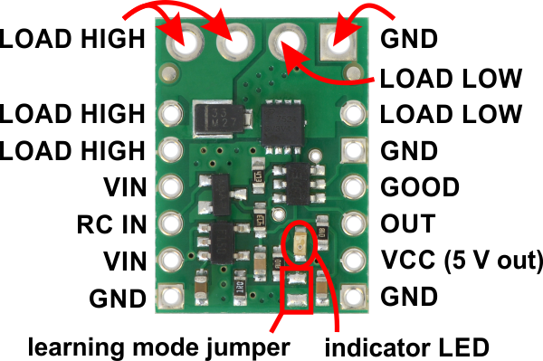
Pololu RC Switch with Medium Low-Side MOSFET, labeled top
view.
The Pololu RC Switch with Medium Low-Side MOSFET has 12 smaller through holes spaced 0.1″
apart that fit 0.1″ header pins and four larger holes that fit 3.5 mm screw terminals.
RC interface
The GND, VIN, and RC IN pins make up the switch’s RC interface and can be connected directly to
an RC receiver or servo controller:
• The GND pin is the ground or reference voltage.
• The VIN pin is the power input.
• The RC IN pin is the RC signal input. The switch measures the width of pulses on this line
and uses that to decide whether to activate or not.
Power
The VIN pins power the basic functions of the board and need to be connected to a power source
between 2.5 V to 16 V. This allows the board to be powered from a 4- or 5-cell NiMH or NiCD battery
pack through an RC receiver or separately.
The VCC pin connects to the output of the onboard regulator and is 5 V when the board is powered
with a source that is greater than or equal to 5 V and approximately equal to VIN when it is below 5 V.
Pololu RC Switch User’s Guide © 2001–2017 Pololu Corporation
4. RC Switch with Medium Low-Side MOSFET Page 18 of 45